Constant-current constant-voltage circuit

A technology of constant current, constant voltage and voltage stabilizing circuit, applied in the direction of electric light source, electrical components, adjusting electrical variables, etc., can solve the problem of inability to cut off the channel current, and achieve the effect of saving power consumption, high efficiency and reducing circuit components

Inactive Publication Date: 2009-07-08
NANKER GUANGZHOU SEMICON MFG
View PDF0 Cites 11 Cited by
  • Summary
  • Abstract
  • Description
  • Claims
  • Application Information

AI Technical Summary

Problems solved by technology

When a negative voltage is applied between the gate and the source, the channel can be cut off, and the conduction current is zero. The gate voltage at this time is defined as the turn-on voltage, but if the channel concentration is too thick and the depth is too deep, the gate Pole will not be able to intercept the channel current
The depletion-type MOS transistor is not as convenient as the enhancement-type MOS transistor in logic application because the drain-source current is turned on at a constant current when the gate and source voltages are zero, so it has not been isolated by the industry. Make a device to use

Method used


Image

  • Constant-current constant-voltage circuit
  • Constant-current constant-voltage circuit
  • Constant-current constant-voltage circuit

Examples


Embodiment 1

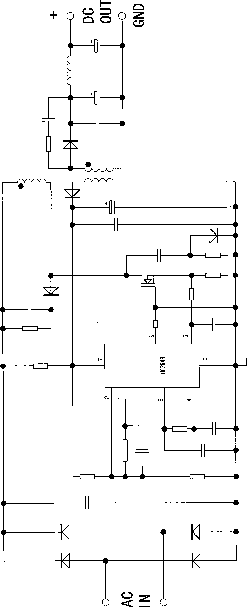
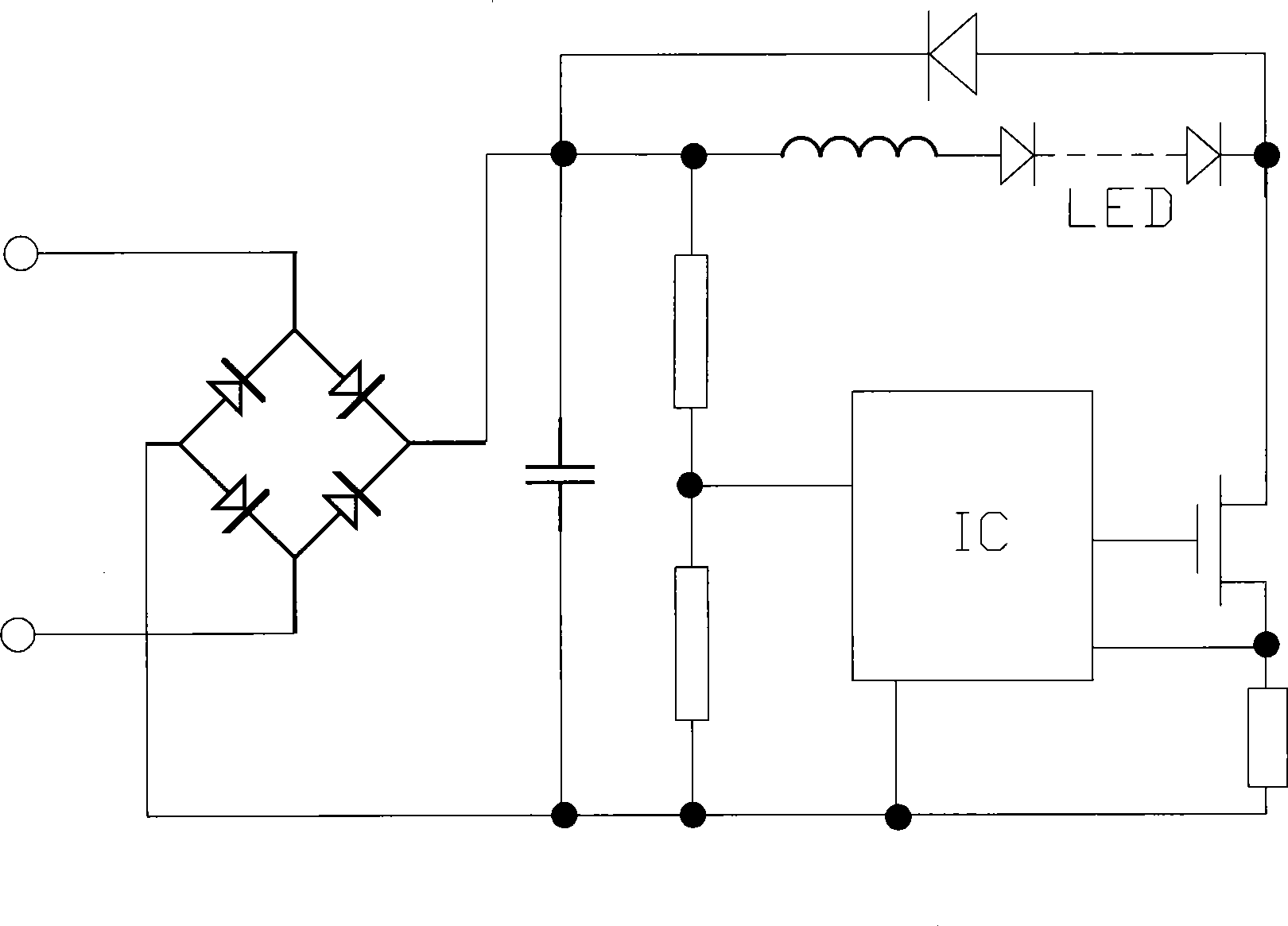
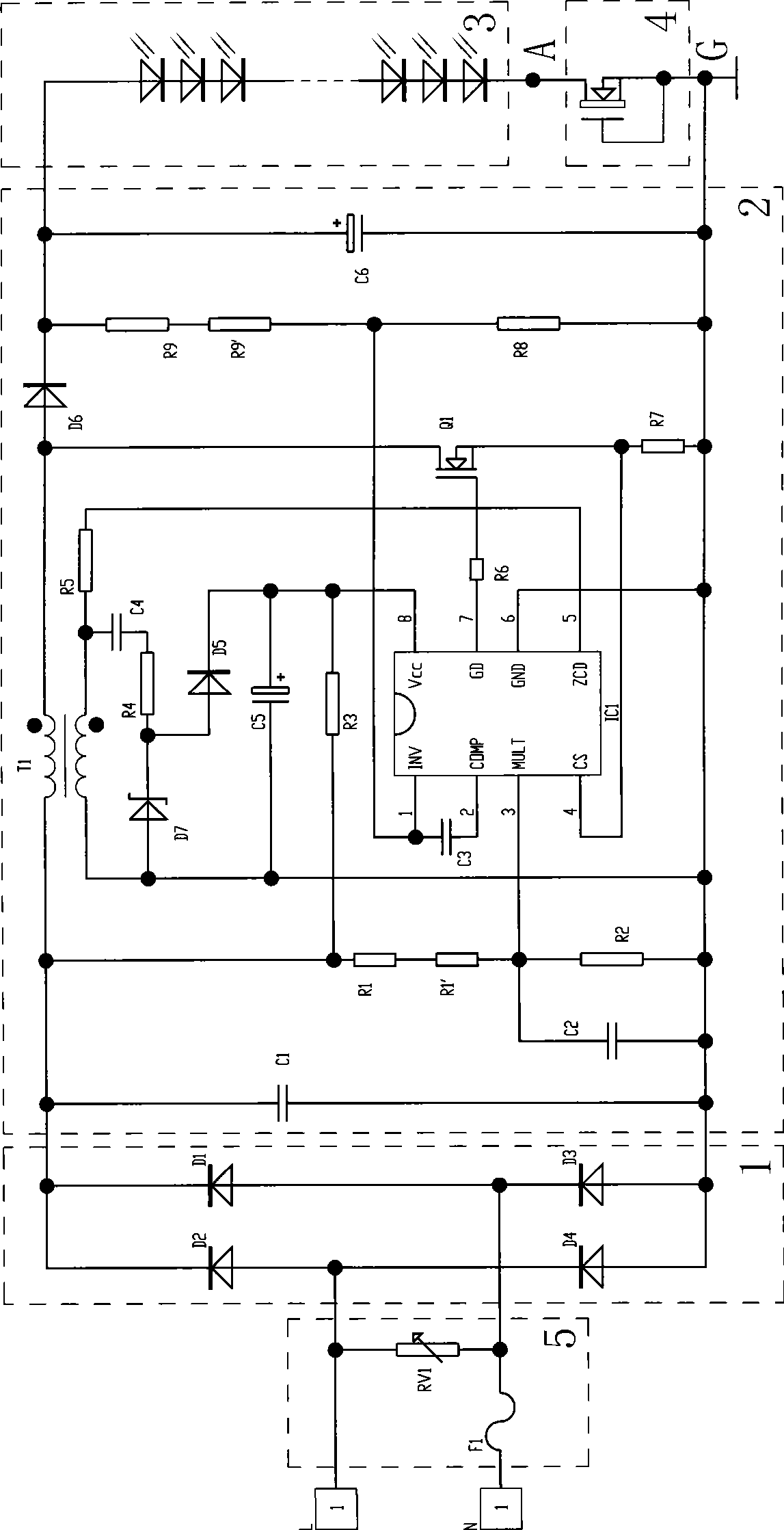
[0022] Such as image 3 As shown, the constant current and constant voltage circuit of this embodiment includes a rectification circuit 1, a voltage stabilization circuit 2, a load 3, a constant current source device 4, and a short circuit protection circuit 5. The output of the output terminal of the circuit 2 becomes constant-voltage direct current and then flows through the load 3. The rectifier circuit 1 adopts a bridge rectifier circuit composed of four rectifier diodes D1, D2, D3, and D4. The short-circuit protection circuit 5 includes a fuse F1 and a varistor RV1 for overcurrent and short circuit protection, connected between the input terminal of the AC power supply and the rectifier circuit 1, the voltage stabilizing circuit 2 is a switching power supply, and the constant current source device 4 is a depletion type field effect transistor, the drain of the depletion type field effect transistor is a contact, the source and the gate of the depletion type field effect t...

Embodiment 2

[0032] like Figure 4 As shown, the difference between this embodiment and Embodiment 1 is that the load 3 of this embodiment includes four groups of several LEDs connected in series, each group of LEDs is connected in series with one of the constant current source devices 4, The four groups connected in series are connected in parallel between the output terminal of the voltage stabilizing circuit 2 and the ground terminal G to form a loop, so there are four constant current source devices 4 in this embodiment. In this embodiment, the method for calculating the number of LEDs connected in series in each group is the same as that in Embodiment 1.

[0033] The remaining features of this embodiment are the same as those of Embodiment 1.

Embodiment 3

[0035] like Figure 5 As shown, the difference between this embodiment and Embodiment 1 is that: the load 3 of this embodiment includes four groups of several LEDs connected in series, each group of LEDs is connected in parallel and then connected with one of the constant current source devices 4. connected in series and in parallel between the output terminal of the voltage stabilizing circuit 2 and the ground terminal G to form a loop. That is, there is only one constant current source device 4 in this embodiment.

[0036] The remaining features of this embodiment are the same as those of Embodiment 1.

[0037] Of course, the load 3 of the present invention can also be other loads such as DC powered electronic circuits or DC motors or high-resistance electrothermal loads. When using these loads, the constant current and constant voltage circuit of the present invention also has the advantages of the above-mentioned embodiments advantage.


PUM


Abstract

The invention discloses a circuit having two functions of constant current and constant voltage at the same time. The constant current and constant voltage circuit has the advantages of simple structure, high efficiency, low power consumption and energy conservation, and can prolong the service life of a load. The constant current and constant voltage circuit comprises a rectification circuit (1), a voltage stabilizing circuit (2) and a load (3). Alternating current is rectified by the rectification circuit (1), then output from the output end of the voltage stabilizing circuit (2), and converted into constant-voltage direct current to flow through the load (3); and the constant current and constant voltage circuit also comprises a constant-current source device (4) connected between the output end (A) of the load (3) and the grounding end (G) of the whole circuit. The invention can be widely applied to the field of constant current and constant voltage circuit.

Description

technical field [0001] The invention relates to a constant current and constant voltage circuit. Background technique [0002] At present, the application of LEDs is becoming more and more extensive, and LED lamps for daily indoor and outdoor lighting are also becoming more and more popular. Current LED drive circuits are generally provided with a separate current-stabilizing or voltage-stabilizing circuit, and there is no circuit with both constant-current and constant-voltage functions. figure 1 It is an existing isolated switching power supply voltage stabilizing circuit. The so-called "isolated" means that the ground terminals on both sides of the transformer are independent. After working for a long time, its conduction voltage will drop, so if the voltage across the LED remains constant, its operating current will increase. Therefore, in the actual application of the voltage stabilizing circuit, after a period of use, the phenomenon that the LED is burned due to the ...

Claims


Application Information

Patent Timeline
Patent Type & Authority Applications(China)
IPC IPC(8): G05F1/46H05B33/08H05B44/00
Inventor 吴俊纬
Owner NANKER GUANGZHOU SEMICON MFG
Why Eureka
Try Eureka