Full-optical-fiber laser resonance cavity and production process thereof

A technology of lasers and resonators, applied in the structure/shape of optical resonators, the structure/shape of active media, etc., can solve the problems of difficult packaging of pump light-coupled fiber lasers, unfavorable practicality and commercialization of fiber lasers, etc. The preparation method is simple and easy, and the transmission loss is small

Inactive Publication Date: 2009-07-08
INST OF IND TECH GUANGZHOU & CHINESE ACADEMY OF SCI +1
View PDF0 Cites 5 Cited by
  • Summary
  • Abstract
  • Description
  • Claims
  • Application Information

AI Technical Summary

Problems solved by technology

[0006] The passive optical fiber ring is formed by directly connecting two output ends of a fiber coupler, or connecting an input end with an output end. The coupler acts as a feedback of the cavity mirror to form a resonant cavity. The beam splitting ratio of the laser is similar to the reflectivity of the F-P cavity mirror, which determines the fineness of the resonator. These two methods bring great difficulties to the coupling of the pump light and the packaging of the fiber laser, which is not conducive to the practicality of the fiber laser. and commercialization, which are particularly affected by external environmental factors

Method used


Image

  • Full-optical-fiber laser resonance cavity and production process thereof
  • Full-optical-fiber laser resonance cavity and production process thereof

Examples


Embodiment Construction

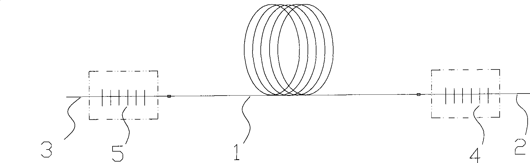
[0021] Such as figure 1 , figure 2 Shown, a kind of all-fiber laser resonator, it comprises doped double-clad fiber 1, the end of this doped double-clad fiber 1 away from the pump source is the front end, and the end close to the pump source is the back end, The resonant cavity also includes a front-end single-mode double-clad fiber 2, a rear-end single-mode double-clad fiber 3, a front-end single-mode double-clad fiber 2, a rear-end single-mode double-clad fiber 3 and a doped double-clad fiber 1 The mode field of the doped double-clad fiber 1 is matched, the front-end single-mode double-clad fiber 2 and the rear-end single-mode double-clad fiber 3 are respectively fused to the front end and the rear end of the doped double-clad fiber 1, and the front-end single-mode double-clad fiber 2, The rear single-mode double-clad optical fiber 3 is engraved with a front-end fiber Bragg grating 4 and a rear-end fiber Bragg grating 5 respectively. The wavelength bandwidths of the front-...


PUM

PropertyMeasurementUnit
reflectanceaaaaaaaaaa

Abstract

The invention discloses a full-optical fiber laser resonant chamber and a preparation method thereof. The resonant chamber comprises a doped double-cladding fiber, a front-end single-mode double-cladding fiber and a back-end single-mode double-cladding fiber. The mode fields of the fibers are matched with each other. The front-end single-mode double-cladding fiber and the back-end single-mode double-cladding fiber are joined with the front end and the back end of the doped double-cladding fiber by means of fusion. A front-end fiber grating and a back-end fiber grating are scribed on the front-end single-mode double-cladding fiber and the back-end single-mode double-cladding fiber respectively. The wavelength bandwidths of the front-end fiber grating and the back-end fiber grating are at least partially overlapped; the reflectivity of the front-end fiber grating is lower than the reflectivity of the back-end fiber grating. In the preparation method, the fiber gratings are scribed on the front-end single-mode double-cladding fiber and the back-end single-mode double-cladding fiber which are joined to the two ends of the doped double-cladding fiber by means of fusion and the mode fields thereof are matched with each other. The preparation method is simple and easy to be used; the performance of the product is improved; and the requirement of an optical fiber laser can be effectively met.

Description

technical field [0001] The invention relates to an all-fiber laser resonant cavity and a preparation method thereof. Background technique [0002] The concept of double-cladding pumping was first announced in 1988. Since then, cladding-pumped fiber lasers have truly achieved high power output. Double-cladding pumping technology has been widely used in fiber lasers and fiber amplifiers. , high-power double-clad fiber lasers have important application prospects in the fields of space, precision machining, laser radar, laser ranging, and laser medical treatment due to their advantages of compact structure, small volume, high power, and long life. In just over a decade, the single-mode output power of a single double-clad fiber laser has grown from tens of milliwatts to hundreds of watts. Scientists from various countries are still working on developing higher-power fiber lasers. The gain resonator of fiber laser adopts double-lens or fiber circulator structure: [0003] 1. Li...

Claims


Application Information

Patent Timeline
Patent Type & Authority Applications(China)
IPC IPC(8): H01S3/08H01S3/067
Inventor 冉洋任纪康杜卫冲刘伟平
Owner INST OF IND TECH GUANGZHOU & CHINESE ACADEMY OF SCI
Why Eureka
Try Eureka