Square wave-sine wave signal converting method and converting circuit

A signal conversion, square wave signal technology, applied in square wave-sine wave signal conversion circuit, square wave-sine wave signal conversion field, can solve the problem of increasing power consumption, disadvantageous low cost and low power consumption, chip power consumption, area As well as problems such as increasing design complexity, to achieve the effect of reducing design complexity, saving area and power consumption

Inactive Publication Date: 2009-07-08
RDA TECH
View PDF0 Cites 105 Cited by
  • Summary
  • Abstract
  • Description
  • Claims
  • Application Information

AI Technical Summary

Problems solved by technology

In short, the direct filtering method of the filter often needs to achieve the required filtering effect at the cost of increasing power consumption and order, an...

Method used


Image

  • Square wave-sine wave signal converting method and converting circuit
  • Square wave-sine wave signal converting method and converting circuit
  • Square wave-sine wave signal converting method and converting circuit

Examples


Embodiment Construction

[0017] The invention provides a square wave-sine wave signal conversion method, comprising

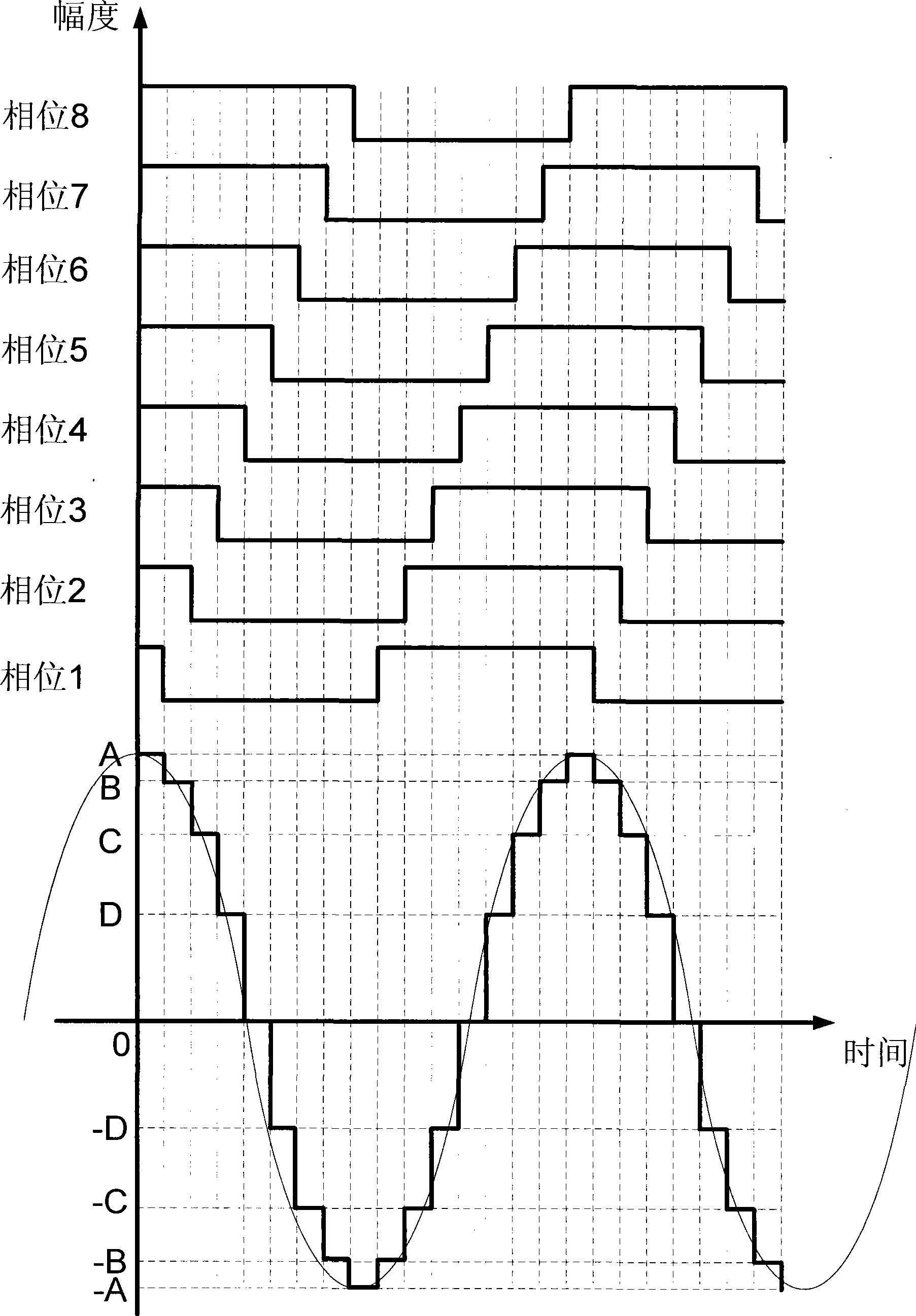
[0018] N square wave control signals with the same cycle and a duty cycle of 50%, where N is an integer greater than 1, the N square wave control signals are arranged in order, and the phase of the latter square wave control signal is higher than that of the previous square wave The phase lag of the control signal is 1 / 2N period;

[0019] N square wave secondary signals are respectively generated by N square wave control signals, the amplitude sum of the N square wave secondary signals is a, and the amplitude of the nth square wave signal is where 1≤n≤N;

[0020] The N square wave secondary signals are superimposed to obtain a pseudo sine wave signal, and the pseudo sine wave signal is filtered to obtain a sine wave signal.

[0021] The N square wave control signals are generated by one square wave control signal.

[0022] figure 1 Shown is a schematic diagram of an embodiment o...


PUM


Abstract

The invention discloses a square wave-sine wave signal transformation method comprising the steps as follows: a square wave signal generates N square wave control signals with the same period; the N square wave control signals arrayed in sequence respectively generate N square wave secondary signals; the amplitude sum of the N square wave secondary signals is a; the amplitude of the square wave signal n is a right type; the N square wave secondary signals are processed through superposition to obtain a false sine wave signal; and the false sine wave signal is processed through filtration to obtain a sine wave signal. A square wave-sine wave signal transformation circuit is also disclosed, and the superposition of the N square wave secondary signals in the method is realized by controlling the superposition of current so as to obtain the sine wave signal. The square wave-sine wave signal transformation method and the square wave-sine wave signal transformation circuit avoid adopting a higher order high-frequency filter directly, greatly save the area and the power consumption of a chip, and reduce the design complexity.

Description

technical field [0001] The invention relates to an electric signal conversion method, in particular to a square wave-sine wave signal conversion method. The invention also relates to an electric signal conversion circuit, especially a square wave-sine wave signal conversion circuit. Background technique [0002] In some digital-analog mixed signal systems, it is often necessary to extract the fundamental frequency of a square wave or a signal similar to a square wave, that is to say, it is necessary to extract a sine wave with a frequency of 1 / T from a digital signal with a period of T. , and remove high-order harmonics, especially in the modulation process of some communication systems, there are relatively strict regulations on the transmission power spectrum to prevent interference with the reception or transmission of the communication system and other communication systems, while high The existence of sub-harmonics often makes the modulation spectrum fail to meet the e...

Claims


Application Information

Patent Timeline
IPC IPC(8): H03B28/00
Inventor 杜定坤魏述然赵春
Owner RDA TECH
Why Eureka
Try Eureka