
Electricity-oil dual-power laneway loader-digger transmission separating mechanism and chassis driving device

A backhoe loader and transmission separation technology, which is applied to the arrangement of multiple prime movers of the power unit, the general power unit, and the air pressure power unit, etc., can solve the problems of high noise, low energy utilization rate, expensive fuel, etc. Achieve the effect of strong climbing ability and good passability of the whole machine

Inactive Publication Date: 2009-07-15
GONGYI CITY XINHUA MACHINERY FACTORY
View PDF0 Cites 1 Cited by
  • Summary
  • Abstract
  • Description
  • Claims
  • Application Information

AI Technical Summary

Problems solved by technology

However, for small-scale operations with relatively fixed positions, the internal combustion engine has its disadvantages: it needs to burn more expensive fuel, discharge exhaust gas, pollute the environment, make a lot of noise, and is not very convenient to operate
[0003] In the field of excavation, loading and transportation, it is usually necessary to combine excavation, loading and transportation. The current backhoe loader only works together with an internal combustion engine (such as a diesel engine) and a gear pump driven by an internal combustion engine, that is, it relies on The internal combustion engine is the power for walking, and the internal combustion engine is still used to drive the gear pump for excavation and loading during excavation and loading, resulting in inflexible operation during excavation and loading operations, low energy utilization rate, and the defects of exhaust gas and noise polluting the environment

Method used


Image

  • Electricity-oil dual-power laneway loader-digger transmission separating mechanism and chassis driving device
  • Electricity-oil dual-power laneway loader-digger transmission separating mechanism and chassis driving device
  • Electricity-oil dual-power laneway loader-digger transmission separating mechanism and chassis driving device

Examples


Embodiment 1

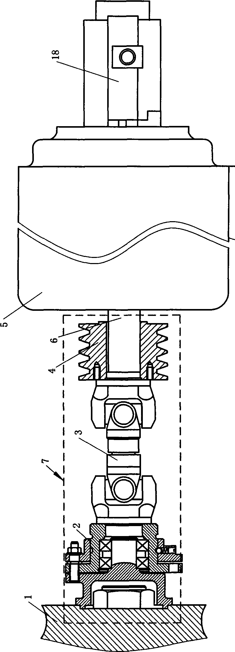
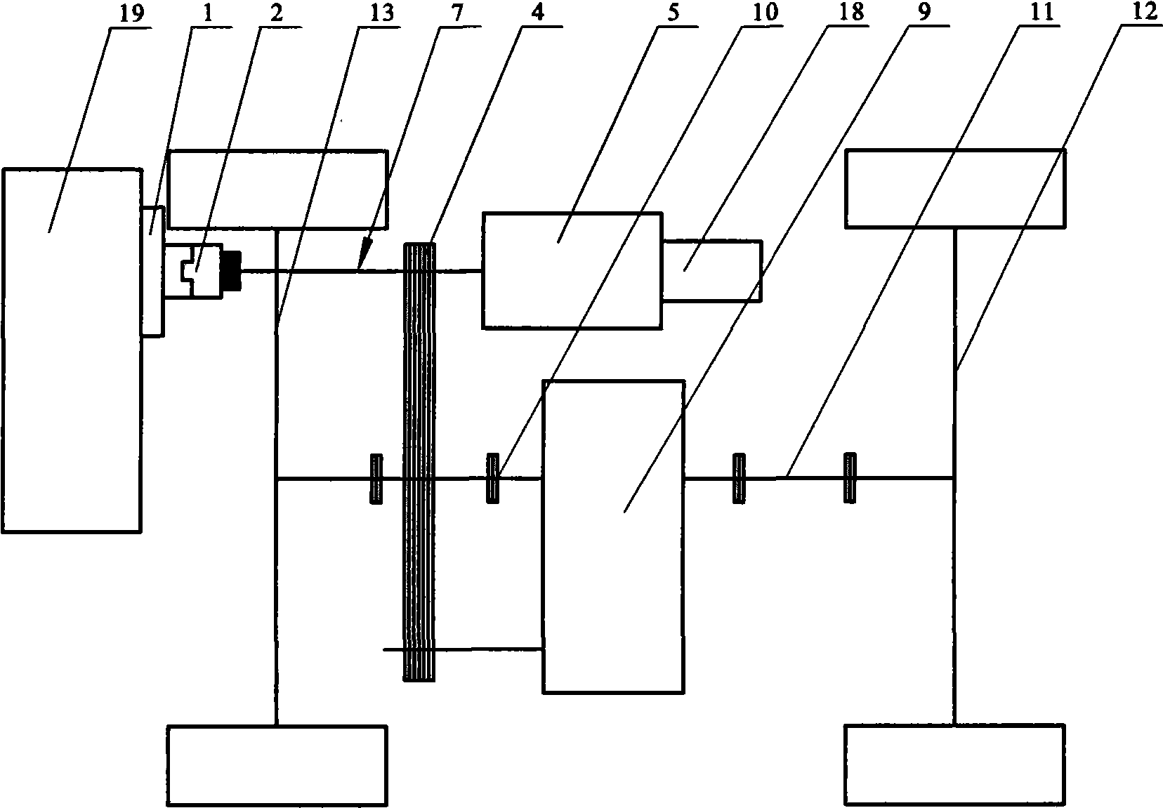
[0025] Embodiment one: see figure 1 , image 3 , an electric oil dual-purpose roadway backhoe loader transmission separation mechanism and chassis drive device, characterized in that the output shaft 1 of the internal combustion engine is coaxially connected with the output shaft 6 of the electric motor 5, and a transmission mechanism 4 is arranged on the coaxial. The coaxial shafts are connected through the cross coupling 3, which is beneficial to overcome the transmission quality affected by a certain swing amplitude caused by vibration and other reasons. In addition, a clutch 2 is also connected to the output shaft of the internal combustion engine 1 to ensure that the internal combustion engine is disconnected from the coaxial shaft in time when the internal combustion engine is not working, so as to facilitate the operation of the electric motor 5 . The above connection relationship is that the output shaft 1 of the internal combustion engine 19, the clutch 2, the Oldham...

Embodiment 2

[0026] Embodiment 2: The accompanying drawings are not drawn, and the meaning is basically the same as Embodiment 1, and the similarities will not be repeated. The difference is that a clutch is also provided between the driving shaft of the transmission mechanism and the output shaft of the motor. Compared with Embodiment 1, when the internal combustion engine is working (when driving the locomotive), it can be disconnected from the output shaft of the motor, and when the motor starts to work, it is guaranteed that the output shaft at one end of the motor or the output shaft at the other end directly drives the transmission. Institutions get to work. The gear pump can be connected with the output shaft at the other end of the motor or can be connected with the coaxial transmission.

Embodiment 3

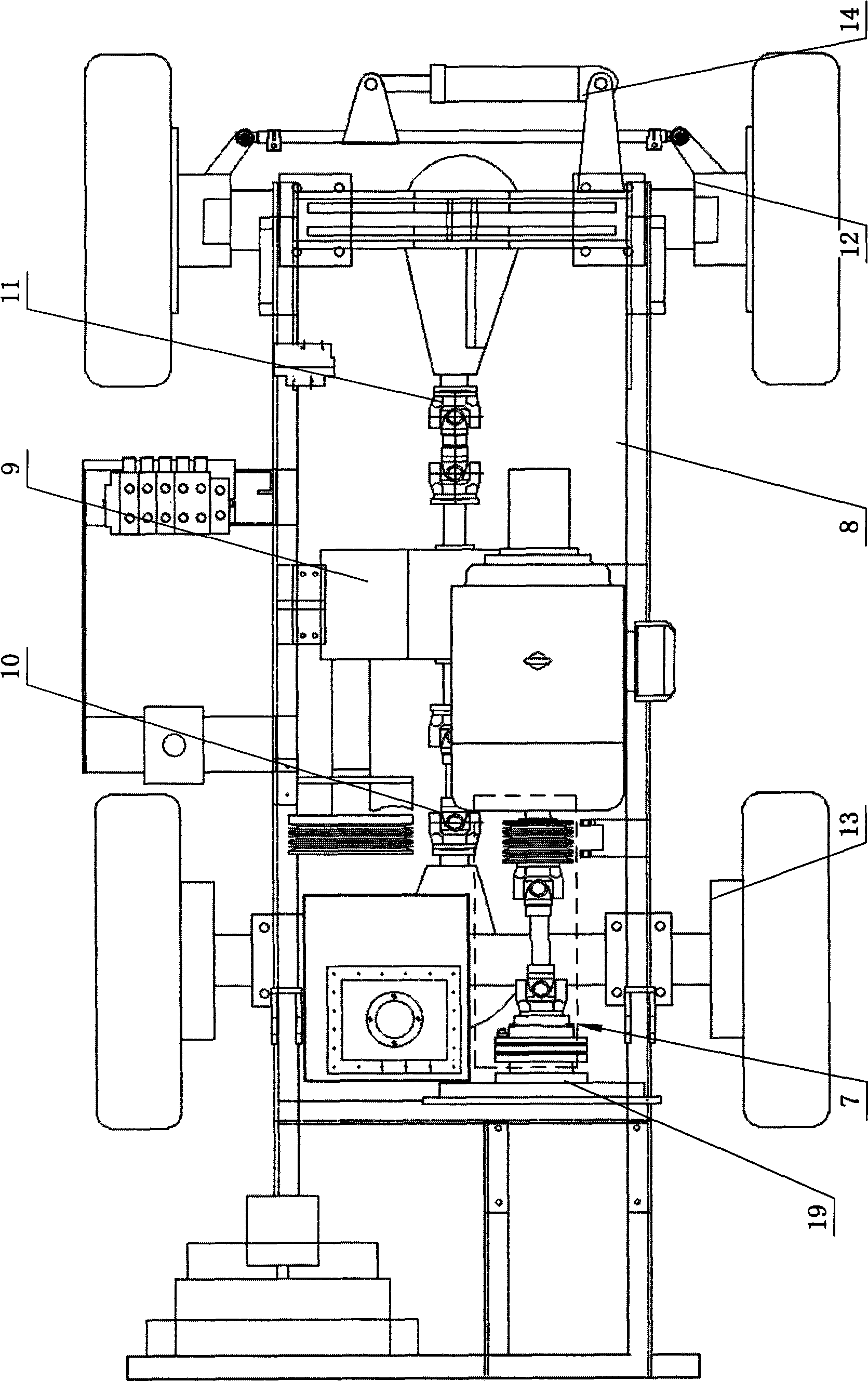
[0027] Embodiment three: see figure 1 , figure 2 , image 3 , Figure 4 , a chassis driving part of an electric-oil dual-purpose roadway backhoe loader, including a chassis 8, a driving mechanism positioned on the chassis 8, a transmission mechanism 4, front and rear axles 12, 13 and wheels installed on both sides thereof, the driving mechanism It includes a power unit, a clutch 2 and a gearbox 9, wherein the power unit is a coaxial dual-power driving machine composed of an electric motor 5 and an internal combustion engine 19, that is, the internal combustion engine 19 is coaxially connected with the electric motor 5, and a transmission mechanism ( Pulley) 4. Internal combustion engine 19 (such as diesel engine) on the complete machine chassis 8 is used for the power of hydraulic pressure walking, drives clutch 2, power transmission shaft (coaxial), motor pulley 4 and motor 5 by internal combustion engine, and motor pulley 4 is connected the pulley of gearbox 9, thereby m...


PUM


Abstract

The invention relates to a driving and separating mechanism and a chassis driving device of a laneway excavation loader using both electricity and petrol. The driving and separating mechanism comprises an internal combustion engine, wherein an output shaft, a clutch and a shaft joint of the internal combustion engine, a main drive shaft of the driving mechanism, and an output shaft of an electric motor are sequentially and coaxially connected in a transmission way; the chassis driving device comprises a chassis, the driving mechanism positioned on the chassis comprises an coaxial double-power driving device, a clutch and a gear-box, and the coaxial double-power driving device consists of the electric motor and the internal combustion engine. The driving and separating mechanism and the chassis driving device adopt the coaxiality of the electric motor and the output shaft of a diesel engine as double power to be used in a matching way, thereby not only ensuring the normal running and transportation operation of a locomotive, but also being convenient for flexibly adopting electrical power as power during excavation and loading operation. The diesel engine is coaxial with the electric motor, and is controlled by the clutch. The internal combustion engine brings larger power which is convenient for transportation and running during four-wheel driving. The invention has the advantages of simple structure and convenient and flexible operation, and is particularly applicable to numerous popularization and application in excavation and loading industry.

Description

1. Technical field: [0001] The invention relates to a driving chassis part for a loader in the field of roadway excavation, in particular to a transmission separation mechanism and a chassis driving device for a roadway digging loader with dual-purpose electric and oil. 2. Background technology: [0002] At present, the locomotives used in the field of excavation, loading and transportation all use internal combustion engines as the main power (for example, heavy backhoe loaders are driven by diesel engines). Using internal combustion engines as transportation power has its advantages: the fuel used in transportation tools is easy to carry, and it can be carried by itself. Enough fuel to go a long way. However, for small-scale operations with relatively fixed positions, the internal combustion engine has its disadvantages: it needs to burn more expensive fuel, discharge exhaust gas, pollute the environment, make a lot of noise, and be inconvenient to operate. Electric locom...

Claims


Application Information

Patent Timeline
Patent Type & Authority Applications(China)
IPC IPC(8): B60K17/02B60K6/20
Inventor 刘建华吴玉环刘天一张天佑
Owner GONGYI CITY XINHUA MACHINERY FACTORY
Learn More