Self-sealing nitrogen circulating cooling method and apparatus

A circulating cooling and self-sealing technology, applied in the field of metallized pellet production in the iron and steel industry, can solve the problems of small temperature difference between inlet and outlet cooling water, inability to recycle waste heat, affecting the metallization rate of products, etc. Reduce, achieve the effect of continuity

Inactive Publication Date: 2009-07-15
LAIWU IRON & STEEL GRP
View PDF0 Cites 7 Cited by
  • Summary
  • Abstract
  • Description
  • Claims
  • Application Information

AI Technical Summary

Problems solved by technology

Therefore, for continuous production, the cooling method of foreign metallized pellets is mainly indirect water-cooled open cooling, the waste heat loss is relatively large, and the temperature difference between the inlet and outlet of cooling water is only about 15°C
In order to further reduce the oxidation of the pellets, Japan introduces low-concentration nitrogen into the indirect water-cooled cooling cylinder to achieve the purpose of reducing the metallization rate of the pellets by continuously replenishing nitrogen, but the waste heat cannot be recycled, and the pellets are cooled in the cooling cylinder A large amount of powder appears during the tumbling process
The cooling facility of the existing rotary hearth furnace direct reduction process in my country is an indirect water-cooled vibrating cooler developed by Beijing University of Science and Technology. Its structure is simple, but the cooling effect is poor. The metallized pellets are actually exposed to the air, and the surface layer is oxidized, which affects the final metallization rate of the product

Method used


Image

  • Self-sealing nitrogen circulating cooling method and apparatus
  • Self-sealing nitrogen circulating cooling method and apparatus
  • Self-sealing nitrogen circulating cooling method and apparatus

Examples


Embodiment 1

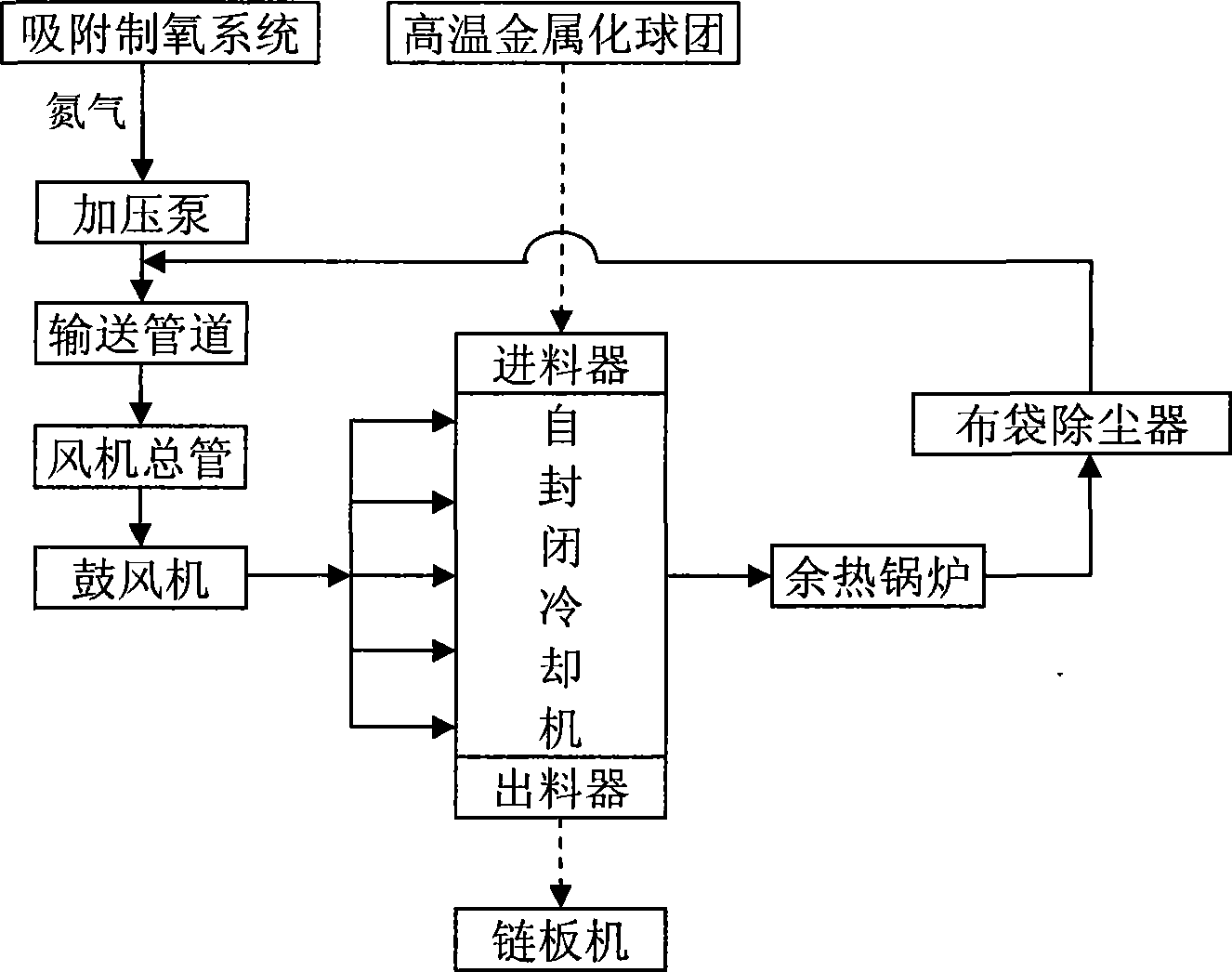
[0032] The nitrogen with a purity of 90% is discharged from the iron and steel plant after oxygen production by adsorption oxygen production technology, and the pressure pump and the pipeline are transported at a distance of 5m. 3 The air volume per hour is sent to the main pipe of the fan. After the supplementary nitrogen is mixed with the circulating gas after waste heat recovery, it is pressurized by the blower and sent to the inlet pipe of the cooler at a speed of 1.3m / s, and enters the grate inside the cooler through the side branch pipe. The 1m wide, 6m long, and 300mm high high temperature metallized pellet material layer area is output from the large flue after heat exchange with the 1000°C high temperature pellets. The temperature of the exhaust gas in the large flue is as high as 580°C. The heat recovery of the waste heat boiler produces 2.6 tons of steam per hour, and the temperature drops to 200°C. It is introduced into the fan main pipe as circulating gas and mixed...

Embodiment 2

[0035] Nitrogen gas with a purity of 80% is discharged from the iron and steel plant after oxygen production by adsorption oxygen production technology, and is sent to the fan main pipe at a gas volume of 15m3 / h through a booster pump and a delivery pipeline. After being pressurized by the blower, it is sent to the inlet pipe of the cooler at a speed of 1.3m / s, and enters the high-temperature metallized pellet material layer area of ​​the cooler with a width of 1.5m, a length of 12m, and a height of 500mm through the side branch pipe. The 1000°C high-temperature pellets are output from the large flue after heat exchange. The temperature of the exhaust gas in the large flue is as high as 600°C. After heat recovery by the waste heat boiler, the steam volume per hour is 5.2 tons, and the temperature drops to 180°C. It is introduced into the fan main pipe as circulating gas and mixed with supplementary nitrogen for recycling.

[0036] The 1000℃ high-temperature metallized pellets ...

Embodiment 3

[0038] The nitrogen with a purity of 50% is discharged from the iron and steel plant after oxygen production by adsorption oxygen production technology, and the pressure pump and the delivery pipeline are separated by 10m 3 The air volume per hour is sent to the main pipe of the fan. After the supplementary nitrogen is mixed with the circulating gas after waste heat recovery, it is pressurized by the blower and sent to the inlet pipe of the cooler at a speed of 1.2m / s, and enters the grate inside the cooler through the side branch pipe. The 1m wide, 10m long, and 400mm high high-temperature metallized pellet layer area is output from the large flue after heat exchange with the 1000°C high-temperature pellets. The temperature of the exhaust gas in the large flue is as high as 550°C. The steam volume per hour is 3.6 tons after heat recovery by the waste heat boiler, and the temperature drops to 180°C. It is introduced into the fan main pipe as circulating gas and mixed with suppl...


PUM


Abstract

The invention provides a self-sealing nitrogen circulating cooling method which comprises the following steps: a. nitrogen discharged after oxygen generation through the absorption oxygen-generation technology in a steel plant is delivered to a blower header pipe through a pressure pump and a delivery pipeline, and the nitrogen in the blower header pipe is mixed with a recycle gas after recovery of heat; b. after pressure is applied to the mixed gas by a blast blower, the mixed gas is delivered to an air inlet pipe of a cooler, enters a material layer zone of a self-cooler through the air inlet pipe, and then is output through a large flue after heat exchange with a high temperature mass at the temperature of 1000 DEGC; and c. the temperature of waste gas in the large flue reaches up to 500-600 DEG C, and then is reduced to 180-230 DEG C after recovery of heat, and the waste gas is again led to the blower header pipe as a recycle gas for mixed cycle utilization with supplementary nitrogen. The technology can realize continuity, stability, recovery of high temperature waste gas and metallization rate of products in production, meet the national policy requirements for energy conservation, emission reduction and cyclic economy, and provide space for reducing production cost.

Description

Technical field [0001] The invention belongs to the technical field of metallized pellet (or direct reduced iron) production in the iron and steel industry, and in particular relates to a circulating cooling technology and device for cooling pellets with nitrogen. Background technique [0002] The production of metallized pellets (direct reduced iron) by rotary hearth furnace direct reduction process is a new ironmaking process developed in the last thirty years. Because this process does not require the preparation of fuel and the deep processing of raw materials, it has a positive effect on the rational use of natural resources and the protection of the human environment, so it has received widespread attention from the metallurgical industry. Cooling is an important process of the process. The pellets at 1000°C are lowered to below 300°C, the remaining heat is recovered, the re-oxidation of the pellets is prevented, the metallization rate of the product is improved, and t...

Claims


Application Information

Patent Timeline
Patent Type & Authority Applications(China)
IPC IPC(8): C22B1/00
Inventor 曾晖李建云薛庆国王静松王延平张英
Owner LAIWU IRON & STEEL GRP
Why Eureka
Try Eureka