Take up type vacuum vapor deposition device

A winding-type, vacuum technology, applied in the direction of vacuum evaporation plating, sputtering plating, ion implantation plating, etc., can solve the problems of reduced cooling effect, weak adhesion force, insufficient irradiation of film 52, etc., to prevent Effect of generation of heat-affected area and prevention of reduction of cooling effect

Active Publication Date: 2009-07-15
ULVAC INC
View PDF1 Cites 5 Cited by
  • Summary
  • Abstract
  • Description
  • Claims
  • Application Information

AI Technical Summary

Problems solved by technology

However, reducing the travel speed of the film will lead to a decrease in production efficiency, so this is not an ideal method
[0007] The generation of the heat-affected region 65 is caused by insufficient irradiation of the electron beam to the thin film 52.
When the amount of electron beam irradiation is small, the adhesion force with the barrel roller 54 will be weakened and the cooling effect will be reduced

Method used


Image

  • Take up type vacuum vapor deposition device
  • Take up type vacuum vapor deposition device
  • Take up type vacuum vapor deposition device

Examples


Embodiment Construction

[0028] Embodiments of the present invention will be described below with reference to the drawings.

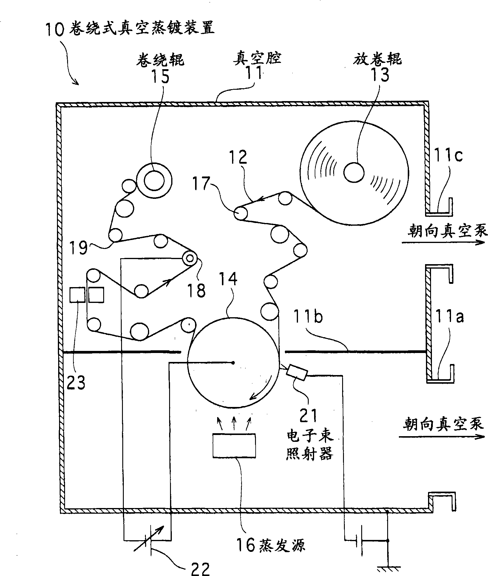
[0029] figure 1 It is a schematic configuration diagram of the roll-to-roll vacuum deposition apparatus 10 in the embodiment of the present invention. The roll-to-roll vacuum evaporation device 10 in this embodiment includes a vacuum chamber 11 , an unwinding roll 13 for a film 12 , a barrel roll 14 for cooling, a winding roll 15 and an evaporation source 16 for an evaporation material.

[0030] The vacuum chamber 11 is connected to a vacuum exhaust system such as a vacuum pump (not shown) through pipe connection portions 11a and 11c, and its interior is decompressed and exhausted to a predetermined vacuum degree. The inner space of the vacuum chamber 11 is partitioned by a partition 11 b into a chamber in which the unwinding roll 13 and the winding roll 15 are disposed, and a chamber in which the evaporation source 16 is disposed.

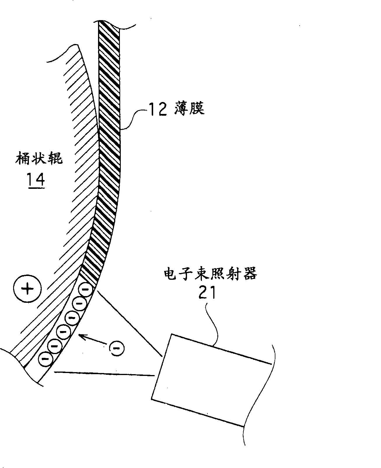
[0031] The film 12 is made of an insulat...


PUM


Abstract

A take up type vacuum vapor deposition device in which an occurrence of a thermally affected area on a film can be suppressed without impairing productivity. The take up type vacuum vapor deposition device (10) has a payout roller (13), a take up roller (15) for taking up a film (12) paid out from the payout roller (13), a cooling roller (14) disposed between the payout roller (13) and the take up roller (15) and cooling the film (12) by being in intimate contact with it, an evaporation source (16) disposed facing the cooling roller (14) and depositing an evaporation material on the film (12), and an electron beam irradiator (21) disposed between the payout roller (13) and the evaporation source (16) and irradiating the traveling film (12) with an electron beam. The electron beam irradiator (21) has a filament (31) for emitting electrons when it is heated by conduction and also has DC generation means for supplying a DC current to the filament (31).

Description

technical field [0001] The present invention relates to a roll-to-roll vacuum evaporation device, which continuously discharges an insulating film in a decompressed atmosphere and makes the film close to a cooling roll for cooling, and winds an evaporation substance onto the film while evaporating and depositing it. Background technique [0002] Up to now, a roll-to-roll vacuum evaporation apparatus in which an evaporated material from an evaporation source is deposited on a long film continuously discharged from an unwinding roll, and the evaporated film is wound by a take-up roll has been developed. It is widely used (for example, refer to the following patent document 1). In such a vacuum vapor deposition apparatus, in order to prevent thermal deformation of the film during vapor deposition, the film formation process is performed while the film is brought into close contact with the peripheral surface of the cooling barrel roll and cooled. Therefore, how to ensure the a...

Claims


Application Information

Patent Timeline
Patent Type & Authority Applications(China)
IPC IPC(8): C23C14/56C23C14/24
CPCC23C14/5826C23C14/562C23C14/02C23C14/541
Inventor 林信博广野贵启多田勋中塚笃小松研二
Owner ULVAC INC
Why Eureka
Try Eureka