Stroboscopic illumination device for pavement detection

A lighting device and road surface detection technology, which is applied in the field of auxiliary lighting devices for road surface detection and shooting, and the field of strobe lighting devices for road surface detection, can solve the problems of high-speed shooting on the road and large-area lighting, unsatisfactory focusing lighting effects, and light source problems. Problems such as uneven lighting can be solved to solve the problems of insufficient lighting and uneven lighting, clear drawing, and improved luminous effect and fill light effect

Inactive Publication Date: 2009-07-22
CHANGAN UNIV
View PDF0 Cites 3 Cited by
  • Summary
  • Abstract
  • Description
  • Claims
  • Application Information

AI Technical Summary

Problems solved by technology

[0005] At present, the stroboscopic light source used for auxiliary illumination of road surface detection area array cameras generally adopts a strobe xenon lamp composed of a single strobe tube, but this light source also has uneven illumination and focused illumination for specific illumination areas. The effect is not ideal and the installation is inconvenient and other defects, which cannot meet the needs of high-speed shooting and large-area lighting for road surface inspection.

Method used


Image

  • Stroboscopic illumination device for pavement detection
  • Stroboscopic illumination device for pavement detection
  • Stroboscopic illumination device for pavement detection

Examples


Embodiment Construction

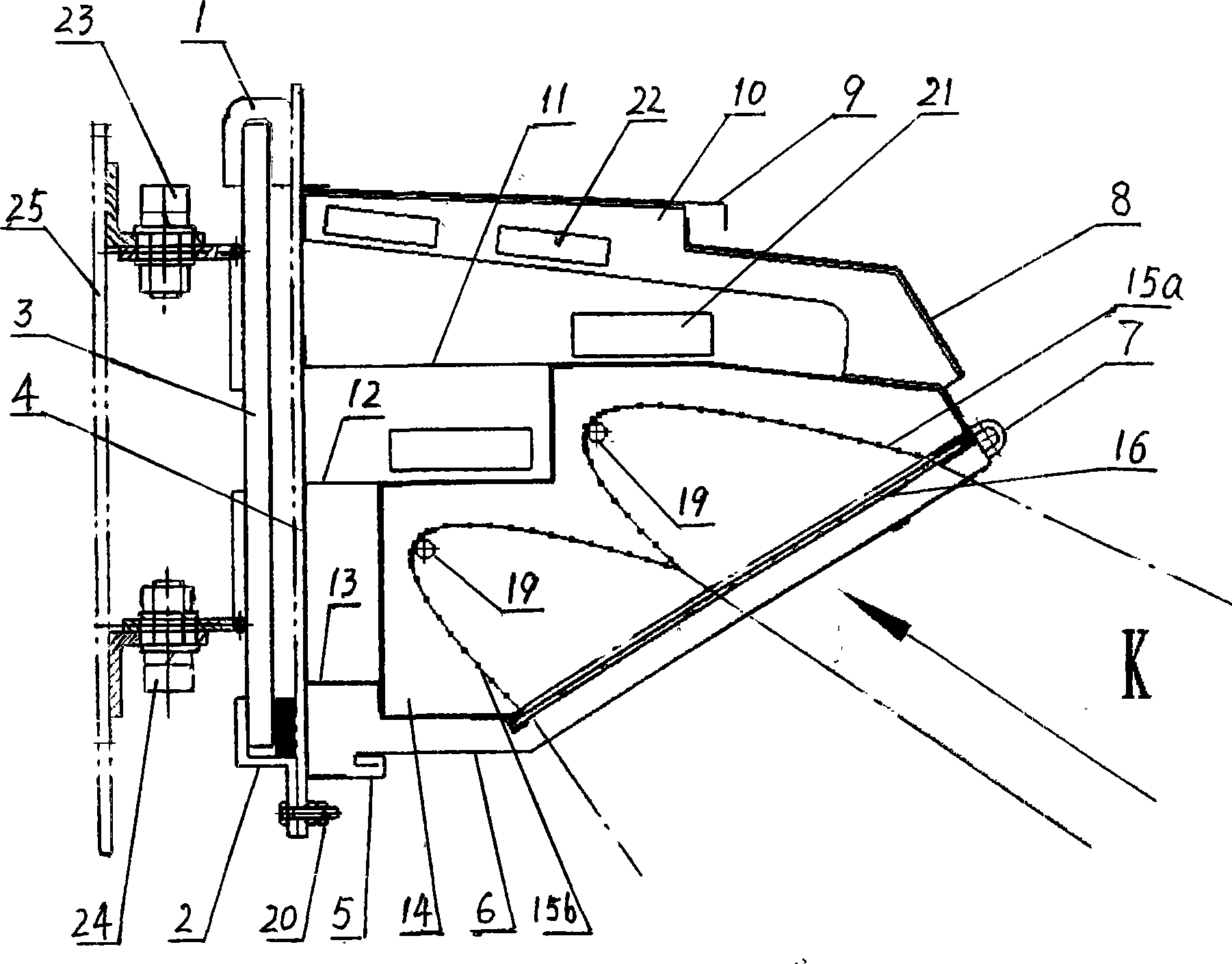
[0013] The content of the present invention will be further described below in conjunction with the accompanying drawings and embodiments, but the actual production structure of the present invention is not limited to the following embodiments.

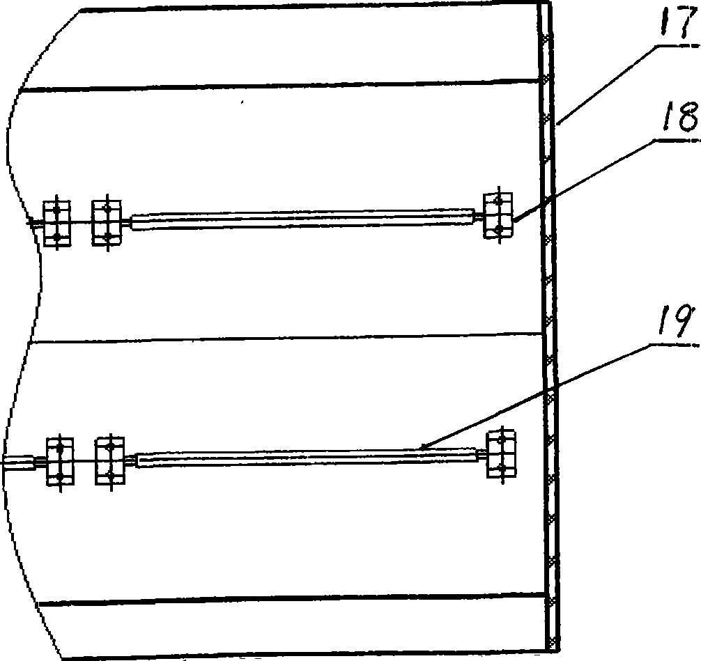
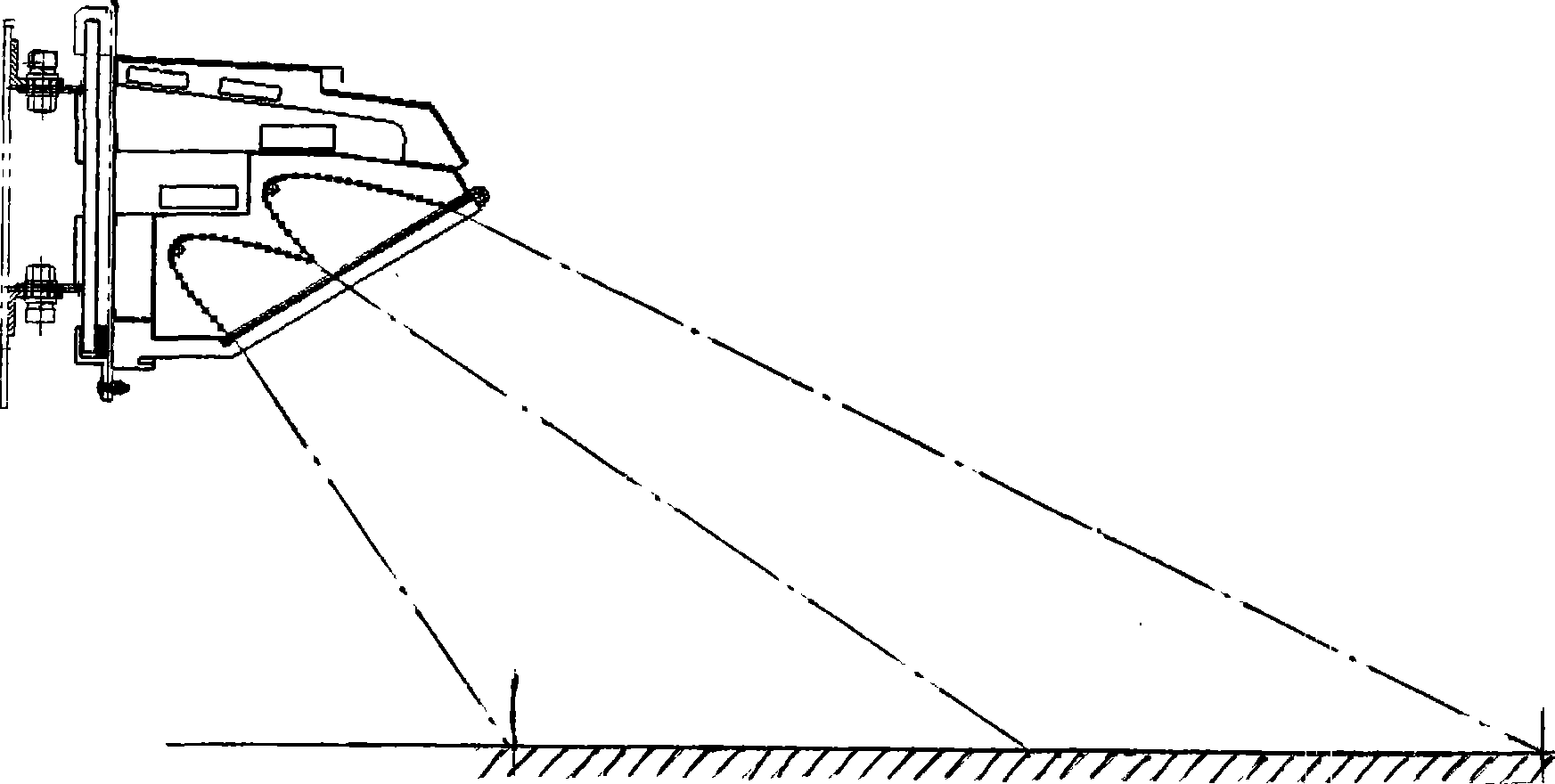
[0014] Referring to the accompanying drawings, the road surface detection strobe lighting device of the present invention is composed of upper and lower hinge supports 23, 24, lamp holder base plate 4, lamp holder, reflector, flash tube 19 and control circuit board 21 and other parts. The lamp holder bottom plate 4 is connected on a transition connecting plate 3 through the hook 1 and the connecting angle plate 2, and the transition connecting plate 3 is connected with the rear terminal plate 25 of the detection vehicle through the upper and lower adjusting hinge supports 23,24. The lamp holder is a shell made up of an upper shell cover and a lower transparent protective cover 6, wherein the upper cover is connected with the lower cove...


PUM


Abstract

The invention relates to a roadway detection stroboscopic illumination device which is provided with a lamp hanger bottom plate connected on a butt plate at the rear end of a detection vehicle by regulating hinged support pieces at the upper part and the lower part; an inclined lamp hanger is installed on the lamp hanger bottom plate, two paraboloid trough type reflecting shades are closely arranged side by side along the slant direction in the lamp hanger, and one or a plurality of flash lighting tube(s) which can project and illuminate towards the slantingly downward direction is/are arranged on the top of the internal groove surface in the two reflecting shades. When the stroboscopic illumination device is in use, after an electric control system starts, the flash lighting tube(s) in the lamp hanger can emit direct light, and the light reflected by the reflecting shades irradiates on the object plane, so that a lighting surface with high brightness is formed. Furthermore, the inclination angle as well as the upper and lower positions of a lamp body can be regulated by the regulating hinged support pieces at the upper part and the lower part, and the device can meet the requirements of illumination with different brightness by the control of a control circuit, thus adapting to the requirements of the installation structure of different illuminating systems in the roadway detection.

Description

technical field [0001] The invention belongs to the technical field of photoelectric applications, and relates to an auxiliary lighting device for road surface detection and photography, in particular to a road surface detection surface photography strobe lighting device. Background technique [0002] In the process of road surface detection, there are two forms for digital image shooting of objects. One is to use a line-scan camera to shoot a narrow band area of ​​the object. Each shot can obtain a one-dimensional image. Through multiple The one-dimensional image is superimposed to obtain a two-dimensional image; the other is to use an area array camera to shoot a specific area of ​​the object, and each shot can obtain a two-dimensional image. [0003] When shooting a relatively moving object, the exposure time of the shooting camera must be shortened, otherwise the captured image may be blurred. Take short exposure time to shoot fast moving objects, and the captured image...

Claims


Application Information

Patent Timeline
Patent Type & Authority Applications(China)
IPC IPC(8): F21S10/06F21V33/00F21V21/14F21V7/10G03B15/05F21Y101/02F21Y103/00
Inventor 宋宏勋马建马荣贵韩毅樊江顺申福林李平
Owner CHANGAN UNIV
Why Eureka
Try Eureka