Light beam transmission apparatus and method

A technology of a transmission device and a transmission method, which is applied in the field of photolithography exposure systems, can solve the problems that cannot be found and corrected in time, the telecentricity and uniformity indicators of the lighting system cannot meet the requirements, etc., and achieve stable telecentricity and uniformity. Effect

Inactive Publication Date: 2009-07-22
SHANGHAI MICRO ELECTRONICS EQUIP (GRP) CO LTD
View PDF1 Cites 17 Cited by
  • Summary
  • Abstract
  • Description
  • Claims
  • Application Information

AI Technical Summary

Problems solved by technology

Although this transmission system can adjust the angle and position of the beam, this adjustment is set before the beam transmission, and is not adjusted in real time. In the process of beam transmission, even if the telecentricity of the lighting system and uniformity indicators do not meet the requirements, and this system cannot be found and corrected in time

Method used


Image

  • Light beam transmission apparatus and method
  • Light beam transmission apparatus and method
  • Light beam transmission apparatus and method

Examples


Embodiment Construction

[0041] The invention will be further described below in conjunction with the accompanying drawings.

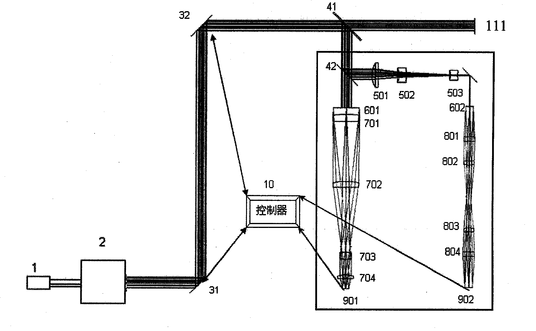
[0042] image 3 It is the overall structure diagram of the beam transmission system of this embodiment, including: a laser 1, a beam expander 2, a first controllable mirror 31 and a second controllable mirror 32, which belong to the beam control unit, 41 and 42 are beam splitters , used to sample and split the beam; 501, 502, and 503 are focusing lenses, which point the beam to the measurement optical path; 601 and 602 are YAG:Ce crystals, which convert the 193nm wavelength of ultraviolet light into visible light; 701, 702, 703, and 704 801, 802, 803 and 804 are relay lenses; 901 and 902 are sensors for measuring the beam position and angle respectively; 10 is a controller; 111 is a diffractive optical element (DOE), which is the exit.

[0043] The beam emitted by the laser light source 1 is incident on the beam control unit after being expanded by the beam expander 2. The b...


PUM


Abstract

The invention provides a beam transmission device which is used for transmitting beams ejected by a laser to a basic illuminating system. A beam steering unit is placed on a beam path of beams; a beam splitter is placed on the beam path of the beams; the beams are divided into a first beam and a second beam after passing through the beam splitter, a beam outlet is arranged on the beam path of the first beam, a beam measuring unit is arranged on the beam path of the second beam, the beam steering unit and the beam measuring unit are both connected with a controller. The beam transmission device of the invention can measure positions and angles of beams in real time and adjust the positions and angles of the beams according to the measurement results, thus ensuring stability of telecenter and uniformity of the illuminating system.

Description

technical field [0001] The invention relates to a photolithography exposure system, and in particular to a light beam transmission device and method in the photolithography exposure system. Background technique [0002] A lithographic exposure system typically includes a light source providing a radiation beam, a beam delivery system, a basic illumination system, a reticle containing a circuit pattern, a projection system, and a wafer for photoresist coating and a wafer alignment stage. The beam transmission system includes a transmission device that diverts and transmits the beam from the beam into the basic lighting system, which is used to incident the beam emitted from the light source on the basic lighting system at the correct angle and position. The basic lighting system illuminates the reticle circuit diagram, and the projection system Projects an image of the illuminated area of ​​the reticle pattern onto the wafer. [0003] Such as figure 1 As shown, the beam tra...

Claims


Application Information

Patent Timeline
Patent Type & Authority Applications(China)
IPC IPC(8): G03F7/20G02B27/00
Inventor 郭勇曹昇炜
Owner SHANGHAI MICRO ELECTRONICS EQUIP (GRP) CO LTD
Why Eureka
Try Eureka