
Gravity hydraulic dead load energy-saving equipment and true triaxial creep experiment system

The technology of an experimental system and energy storage device is applied in the field of gravity hydraulic constant load energy storage device and true triaxial creep experiment system, which can solve the problems of limitation of load value and displacement, increase of experiment cost, complex structure, etc., and achieve structural simple effect

Inactive Publication Date: 2009-07-29
CHINA UNIV OF MINING & TECH (BEIJING)
View PDF0 Cites 18 Cited by
  • Summary
  • Abstract
  • Description
  • Claims
  • Application Information

AI Technical Summary

Problems solved by technology

[0003] The hydraulic pump provides high-pressure liquid for the creep sample device, and loads the coal rock sample through the clamping device. However, during the creep (or volume change) process of the sample, the load applied to the end face of the sample is always at a certain level. The load line fluctuates up and down, and the experimental results cannot reach the strict constant load of the creep test; at the same time, the creep test generally takes a relatively long time, and the hydraulic pump is always in the working state during the test, which causes a lot of energy consumption and increases Experiment fee
[0004] Using the principle of leverage or gear transmission to provide power for creep experiments with heavy objects, the load value (tonnage) and displacement are greatly limited, and it is difficult to provide horizontal loads, so only uniaxial compression creep experiments can be performed. The obtained results are very limited in the understanding of the creep mechanical properties of coal rock samples under complex conditions
[0005] The above-mentioned prior art has at least the following disadvantages: the structure is relatively complex, and it is difficult to provide the requirements for creep dead load

Method used


Image

  • Gravity hydraulic dead load energy-saving equipment and true triaxial creep experiment system
  • Gravity hydraulic dead load energy-saving equipment and true triaxial creep experiment system
  • Gravity hydraulic dead load energy-saving equipment and true triaxial creep experiment system

Examples


specific Embodiment approach

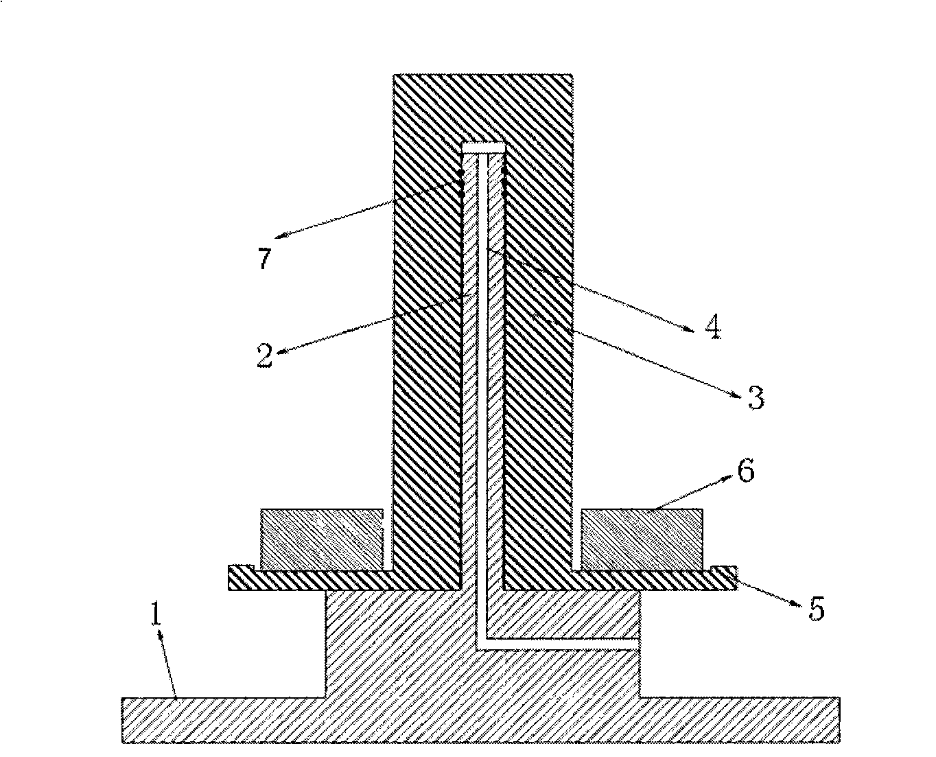
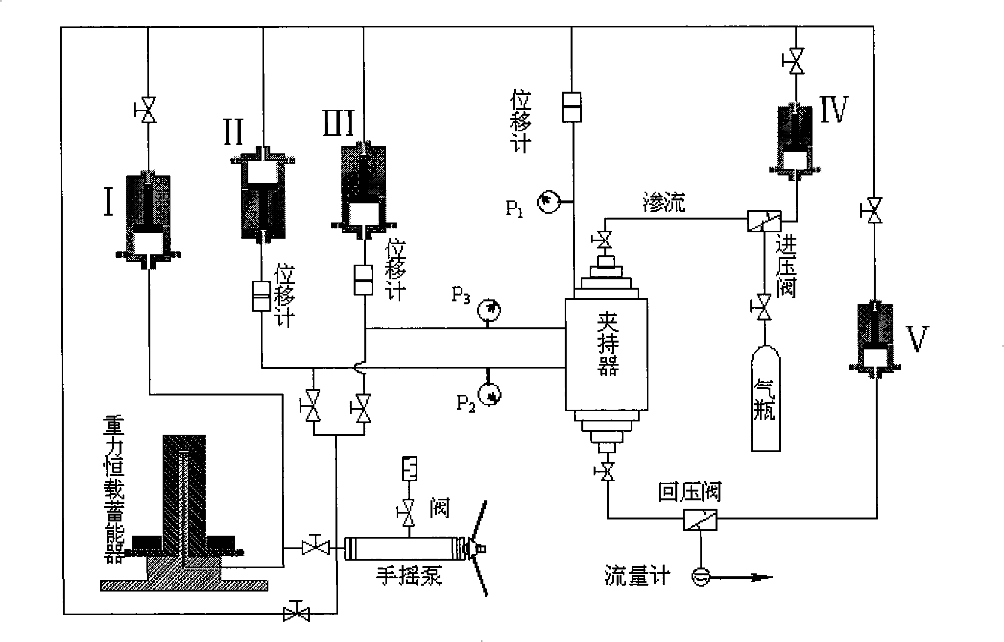
[0034] During the specific implementation, the following steps are included: (1) first calculate the load to be applied to the sample, so as to determine the weight of the weight to be applied, and load the weight to be applied to the cylinder of the energy storage device; (2) place the test piece After putting in the holder, from the holder to the energy storage device, use a vacuum pump to evacuate the air in each section of the closed space in turn, and then use a hand pump to infuse it; (3) Before infusion of the energy storage device, turn off the pressure transformer The shut-off valve on the I outlet pipeline adopts a hand pump to pressurize the energy storage device (input pressure liquid), until the cylinder body on the energy storage device is raised to a certain height, close the hand pump and stop the infusion; (4 ) adjust the temperature of the constant temperature box, open the cut-off valve on the outlet pipeline of the pressure transformer I, carry out the creep...


PUM


Abstract

The invention discloses a gravity hydraulic constant load energy storage device and a true triaxial creep experiment system. The gravity hydraulic constant load energy storage device comprises a fixed piston and a movable cylinder body, the outside of the cylinder body is provided with a carrier platform, when the carrier platform is provided with heavy objects with different weights, a hydraulic loading system is provided with constant loads of different sizes by a fluid infusion hole, and a sample is loaded by the fluid infusion hole and a line. The pressure produced by the heavy objects is balanced by a hand pump so as to supply liquid to the system and provide constant static pressure, and the constant pressure provided by the gravity hydraulic constant load energy storage device can also be changed into different pressures so as to be suitable for axial pressure and side pressure differences in a creep experiment and given pressure differences in a seepage test, thus reducing experimental cost caused by power consumption of the creep experiment.

Description

technical field [0001] The invention relates to a loading test technology, in particular to a gravity hydraulic constant load energy storage device and a true triaxial creep test system. Background technique [0002] In the prior art, there are two kinds of power devices for creep experiments, one is a device that uses a hydraulic pump to load, and the other is a device that relies on the weight of a heavy object to load through a mechanical transmission. [0003] The hydraulic pump provides high-pressure liquid for the creep sample device, and loads the coal rock sample through the clamping device. However, during the creep (or volume change) process of the sample, the load applied to the end face of the sample is always at a certain level. The load line fluctuates up and down, and the experimental results cannot reach the strict constant load of the creep test; at the same time, the creep test generally takes a relatively long time, and the hydraulic pump is always in the ...

Claims


Application Information

Patent Timeline
IPC IPC(8): G01N3/00
Inventor 秦跃平杨小彬聂百胜宋为
Owner CHINA UNIV OF MINING & TECH (BEIJING)
Learn More