Heat pipe performance detection device

A detection device and heat pipe technology, applied in the direction of material thermal development, material thermal conductivity, etc., can solve the problems of inability to meet the detection requirements of mass production process, delayed delivery, unfavorable heat pipe performance, etc.

Inactive Publication Date: 2009-07-29
FU ZHUN PRECISION IND SHENZHEN +1
View PDF0 Cites 11 Cited by
  • Summary
  • Abstract
  • Description
  • Claims
  • Application Information

AI Technical Summary

Problems solved by technology

[0007] However, the above-mentioned Figure 1 and other existing heat pipe performance detection devices generally have the following shortcomings, which are not conducive to accurately evaluating the performance of heat pipes; including:
[0008](1) In order to achieve the close thermal contact between the heat pipe, the heat source and the heat sink, and to accurately measure the wall temperature of the evaporation section and the condensation section of the heat pipe at the same time, the current detection The device is difficult to balance;
[0009](2) The above requirements are more difficult to effectively control when multiple detection devices are used in mass production;
[0010](3) It is difficult to accurately control the effective length of the evaporation section and the condensation section during the rapid full inspection, which is another important factor causing the variation of the performance of the heat pipe;
[0011](4) Heat loss and temperature measurement are susceptible to variation due to the influence of the external environment;
[0012](5) Installation and disassembly are very cumbersome and labor-intensive, so that the conventional heat pipe performance testing device is only suitable for small-scale heat pipe testing on a laboratory scale, and is completely unable to cope with mass production The testing requirements

Method used


Image

  • Heat pipe performance detection device
  • Heat pipe performance detection device
  • Heat pipe performance detection device

Examples


Embodiment Construction

[0029] The heat pipe performance detection device of the present invention will be further described below with reference to FIGS. 2 to 10 .

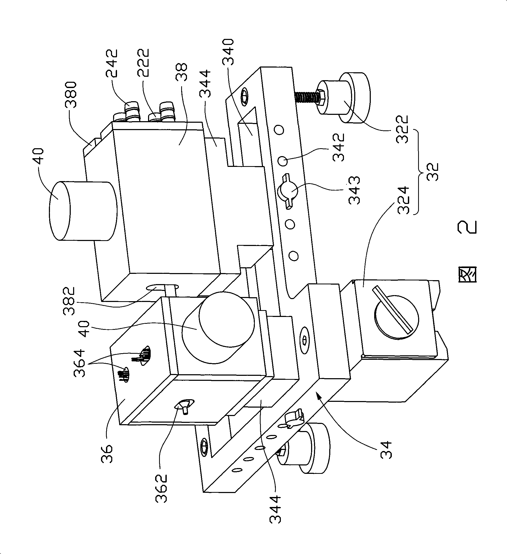
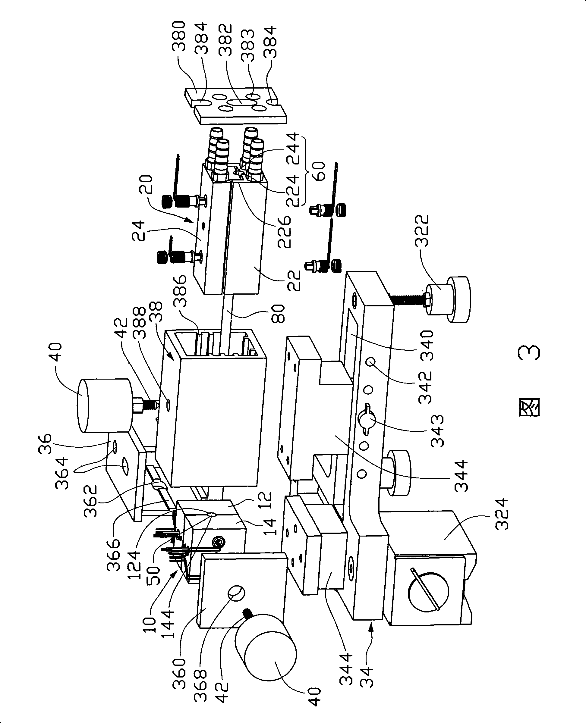
[0030] Fig. 2 is a three-dimensional schematic diagram of the appearance of the first embodiment of the heat pipe performance detection device of the present invention, Fig. 3 is a three-dimensional exploded schematic diagram of Fig. 2, and Fig. 4 is a three-dimensional exploded schematic diagram of the heating assembly in Fig. 2; the detection device mainly includes a The heating element 10 , a heat dissipation element 20 and a bearing seat 30 . in:

[0031]The heating assembly 10 includes a fixed part 12 and a movable part 14 arranged side by side in a horizontal direction. A moving part that can move linearly. At least one of the fixed part 12 and the movable part 14 is made of a material with good thermal conductivity. In this embodiment, both are made of a material with good thermal conductivity as an example. Wherein, at least ...


PUM


Abstract

The invention discloses a heat pipe performance detection device. The heat pipe performance detection device comprises a heating assembly, a heat radiation assembly and a bearing part. The heating assembly and the heat radiation assembly respectively comprise a fixed part and a mobile part which can be relatively separated and united, at least a measuring accommodation part capable of accommodating a heat pipe to be detected is arranged between opposite surfaces of the heating assembly and the heat radiation assembly, at least a temperature sensor is arranged in the middle of the measuring accommodation part, the heating assembly is provided with at least an accommodation aperture communicated with the measuring accommodation part and used for accommodating the temperature sensor and at least an accommodation hole accommodating a heating element for the heat pipe to evaporate heat, the accommodation aperture is perpendicular to an extension direction of the accommodation hole, the heat radiation assembly is provided with at least a cooling structure, the bearing part comprises a locating seat and two adjustment pieces arranged on the locating seat and capable of being slideably adjusted relative to the locating seat, and the two adjustment pieces respective bear the heating assembly and the heat radiation assembly and adjust and locate positions.

Description

technical field [0001] The invention relates to a detection device, in particular to a heat pipe performance detection device. Background technique [0002] The basic structure of the heat pipe is that the inner wall of the closed tube is lined with a porous capillary structure layer that is easy to absorb the operating fluid, while the central space is in a hollow state, and the total amount of pores equivalent to the capillary structure layer is injected into the vacuumed closed tube. The volume of the operating fluid can be divided into an evaporation section, a condensation section, and an adiabatic section in between, according to the relative position of absorbing and dissipating heat. [0003] The working principle of the heat pipe is that when the evaporation section absorbs heat, the liquid-phase operating fluid contained in the capillary structure layer evaporates, and the vapor pressure increases, and the high-enthalpy vapor flow generated is quickly moved along t...

Claims


Application Information

Patent Timeline
IPC IPC(8): G01N25/20G01N25/18G01M19/00
Inventor 刘泰健
Owner FU ZHUN PRECISION IND SHENZHEN
Why Eureka
Try Eureka