Oscillation type silicon micro-gyroscope

A silicon micro-gyroscope and swing-type technology, which is applied to gyroscope/steering sensing equipment, gyroscope effect for speed measurement, instrument and other directions, can solve the problems of gyroscope performance impact and large microelectronic process error, so as to improve sensitivity and Effect of processing error and simplified circuit

Inactive Publication Date: 2011-01-12
NANJING UNIV OF SCI & TECH
View PDF1 Cites 0 Cited by
  • Summary
  • Abstract
  • Description
  • Claims
  • Application Information

AI Technical Summary

Problems solved by technology

Due to the large relative error of the microelectronics process, the processing error has a great impact on the performance of the gyroscope

Method used


Image

  • Oscillation type silicon micro-gyroscope
  • Oscillation type silicon micro-gyroscope
  • Oscillation type silicon micro-gyroscope

Examples


Embodiment 1

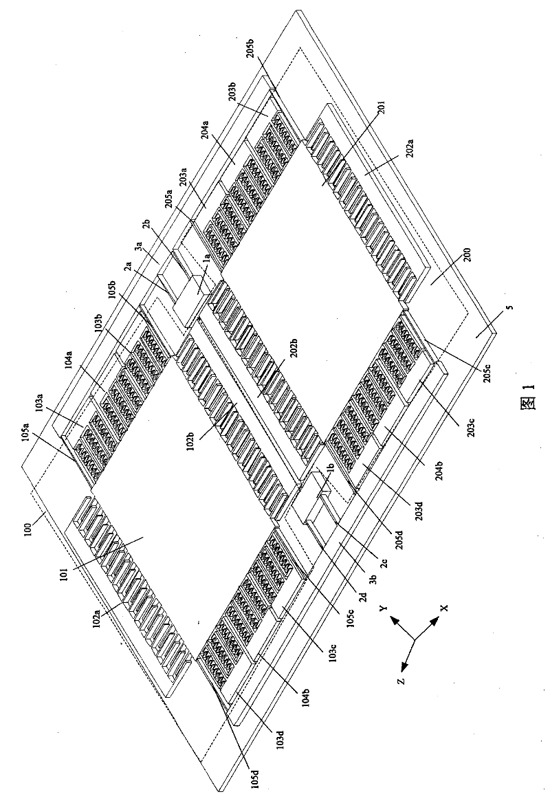
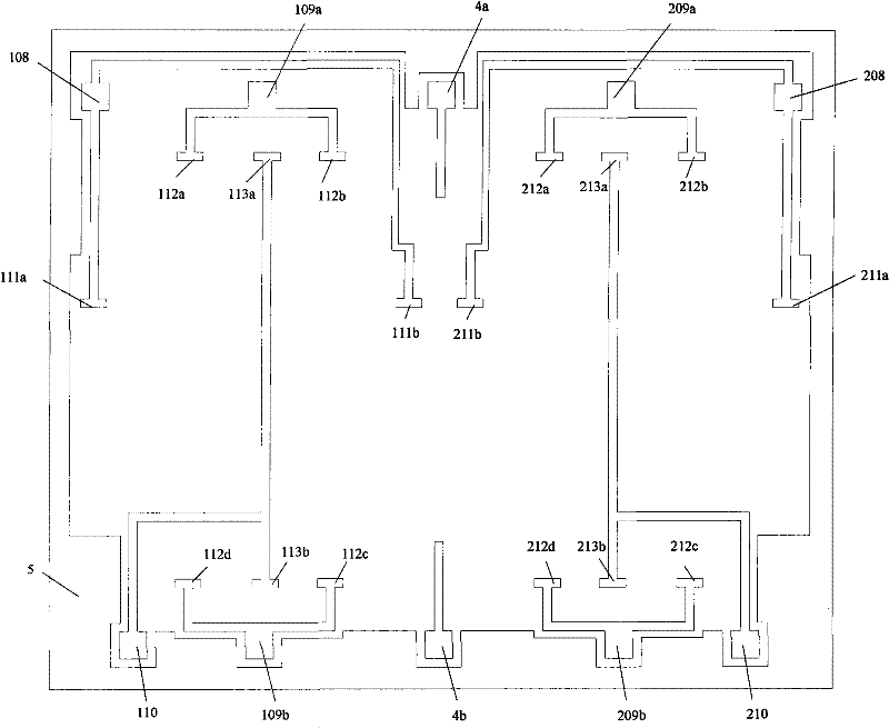
[0012] Example 1: Combining figure 1 , the oscillating silicon micro-gyroscope of the present invention is used to measure the measuring instrument perpendicular to the level of the base. It consists of upper and lower layers. The signal leads on the substrate 5, the signal leads 108, 208, 109a, 109b, 209a, 209b, 110, 210 and the bonding points 4a, 4b, 111a, 111b, 211a, 211b, 112a, 112b, 112c, 112d, 212a, 212b, 212c, 212d, 113a, 113b, 213a, 213b, the upper mechanical structure of the gyroscope is composed of a pair of identical substructures 100, 200, the two substructures 100, 200 are along the Y axis Symmetrically arranged, and respectively connected with the beams 3a, 3b, the beams 3a, 3b are connected to the fixed bases 1a, 1b through two sets of torsion bars, and the fixed bases 1a, 1b are bonded to the lower glass substrate 5, so that the upper layer The mechanical structure of the part is suspended above the lower part of the glass substrate. Each group of torsion bar...

Embodiment 2

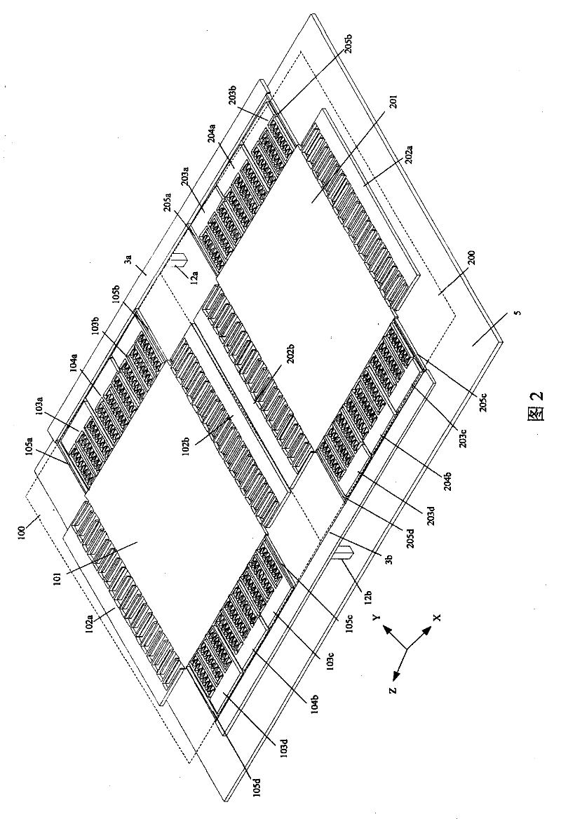
[0013] Example 2: Combining figure 2 , the swing type silicon micro-gyroscope of the present invention is made of upper and lower layers, the upper layer is the gyroscope mechanical structure made on the single crystal silicon wafer, the lower layer is the signal lead wire made on the glass substrate 5, and the lower layer glass lining Signal leads 108, 208, 109a, 109b, 209a, 209b, 110, 210 and bonding points 4a, 4b, 111a, 111b, 211a, 211b, 112a, 112b, 112c, 112d, 212a, 212b, 212c are arranged on the bottom 5. 212d, 113a, 113b, 213a, 213b, the upper mechanical structure of the gyroscope is composed of a pair of identical substructures 100, 200, the two substructures 100, 200 are symmetrically arranged along the detection axis (Y axis), and are respectively connected to the beam 3a , 3b connection, the beams 3a, 3b are connected to the lower glass substrate 5 through two sets of torsion bars 12a, 12b, so that the upper mechanical structure part is suspended above the lower gla...


PUM


Abstract

The invention relates to a wobbly silicon micro gyroscope which comprises an upper layer and a lower layer, wherein a gyroscope mechanical structure which is arranged on a monocrystalline silicon sheet is formed on the upper layer, and a signal lead wire which is arranged on a glass substrate is formed on the lower layer. The signal lead wire and a bonding point are arranged on the glass substrate on the lower layer; the gyroscope mechanical structure on the upper layer comprises a pair of identical minor structures which are symmetrically arranged along the Y axis and are respectively connected with a beam, and the beam is bonded with the glass substrate on the lower layer through two groups of twisting rods to enable the mechanical structure on the upper layer to be suspended above the glass substrate on the lower layer. The twisting rods and the beam are adopted in the invention to enable the gyroscope to rotate around the Z axis, the sensitive movement of the gyroscope is achieved, and the movement decoupling in the driving direction and the detecting direction is achieved. The twisting rods are used for replacing sensitive supporting beams, the amount of the supporting beams is reduced, and the influence of the processing error to the performance of the gyroscope is reduced.

Description

technical field [0001] The invention belongs to micro-electromechanical system and micro-inertia measurement technology, in particular to a swing type silicon micro-gyroscope. Background technique [0002] Micromachined inertial instruments include micromachined gyroscopes (MMG) and micromachined accelerometers (MMA). The use of microelectronic processing technology allows the complete integration of micromechanical structures and required electronic circuits on a silicon chip, thereby achieving a high degree of unity in terms of performance, price, volume, weight, and reliability. Therefore, this type of instrument has a series of advantages (such as small size, light weight, cheap price, high reliability, mass production, etc.), and has broad application prospects in both military and civilian fields. In civilian use, it is mainly used in the automotive industry, industrial monitoring and consumer products and robotics, such as airbags, anti-lock braking systems, yaw rate...

Claims


Application Information

Patent Timeline
Patent Type & Authority Patents(China)
IPC IPC(8): G01C19/56B81B7/02B81C5/00B81C99/00G01C19/5719
Inventor 苏岩裘安萍施芹丁衡高
Owner NANJING UNIV OF SCI & TECH
Why Eureka
Try Eureka