Thermo-electric generation module using LNG cold energy and production method thereof
A thermoelectric power generation module, cold energy technology, applied in the directions of generators/motors, electrical components, etc., can solve the problems of optimization, low performance of thermoelectric materials, etc., and achieve the effect of convenient series connection and no moving parts
- Summary
- Abstract
- Description
- Claims
- Application Information
AI Technical Summary
Problems solved by technology
Method used
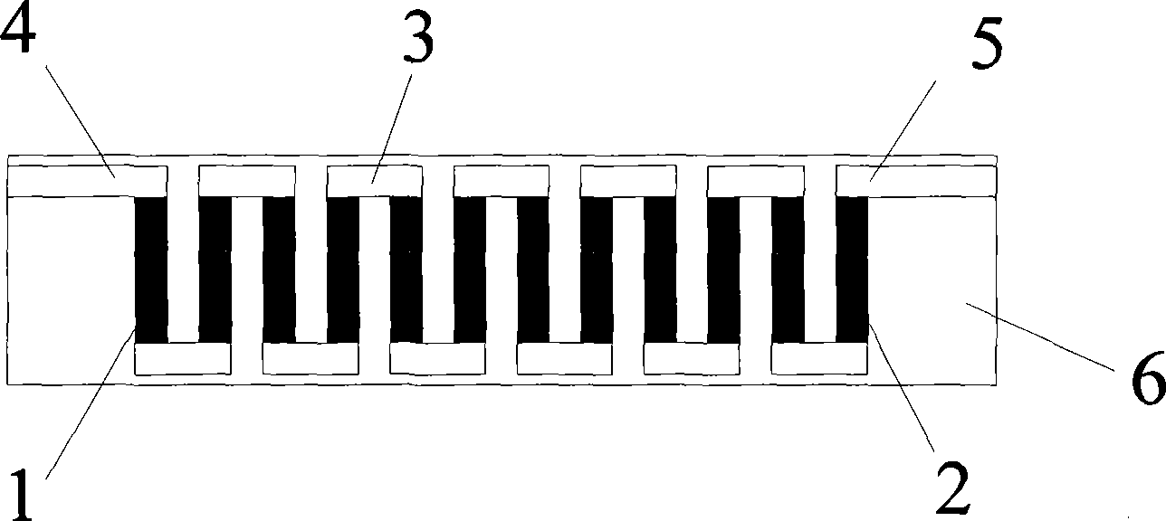
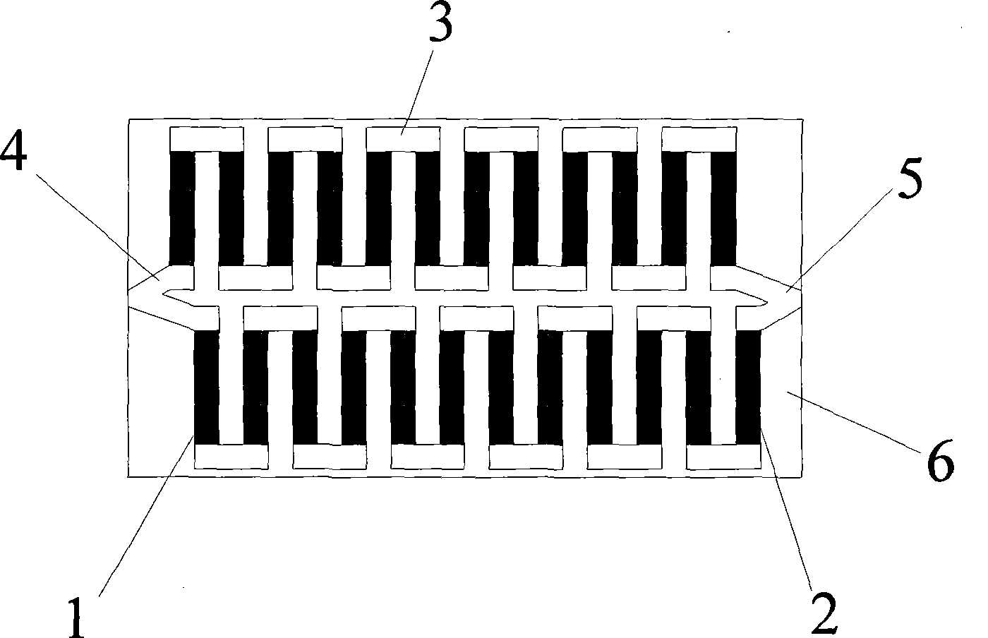
Image


Examples
Embodiment 1
[0037] Mirror polished quartz SiO 2 Glass film negative, the size of the film is 30mm×15mm×2mm; before sputtering, the substrate is treated in acetone, deionized water and anhydrous alcohol with an ultrasonic cleaner for 20 minutes and then dried;
[0038] Preheat the mixed crystals Bi, Te, Pb and Sb at 200°C for 1 hour in an Ar working atmosphere, and then fix the mixed crystals as a target on the cathode of the RF magnetron sputtering system;
[0039] Magnetron sputtering deposition of Bi, Te, Pb mixed crystals on the film, the molar mass ratio of Pb: Bi: Sb = 0.1: 6:1, to prepare P-type nano film; magnetron sputtering deposition of Te, Pb on the film Bi and Sb mixed crystals, the molar mass ratio is Te: Bi: Sb = 0.15: 6:1; N-type nano film sheets are prepared. The preparation parameters of the nano-film material are: working gas is Ar, working pressure is 2.5Mpa, sputtering power is 20W, and the thermoelectric nano-coating obtained by sputtering is 260nm, and the temperature is...
Embodiment 2
[0043] Use polyurethane as the negative film, the size of the film is 50mm×20mm×2mm; before sputtering, the substrate is treated in acetone, deionized water and anhydrous alcohol with an ultrasonic cleaner for 30 minutes and then dried;
[0044] Preheat the mixed crystals Bi, Te, Pb and Sb at 200°C for 1 hour in an Ar working atmosphere, and then fix the mixed crystals as a target on the cathode of the RF magnetron sputtering system;
[0045] Magnetron sputtering deposition of Bi, Te, Pb mixed crystals on the film, the molar mass ratio of Pb: Bi: Sb = 0.15: 6:1, to prepare P-type nano film; magnetron sputtering deposition of Te, Pb on the film Bi and Sb mixed crystals, the molar mass ratio is Te: Bi: Sb = 0.15: 6:1; N-type nano film sheets are prepared. The preparation parameters of the nano-film material are: working gas is Ar, working pressure is 3Mpa, sputtering power is 25W, and the thermoelectric nano-coating obtained by sputtering is 400nm, and the temperature is N at 300℃. ...
PUM
| Property | Measurement | Unit |
|---|---|---|
| thickness | aaaaa | aaaaa |
| thickness | aaaaa | aaaaa |
| thickness | aaaaa | aaaaa |
Abstract
Description
Claims
Application Information