
Large flue gas desulfurization dust-removal system

A technology for desulfurization, dust removal, and flue gas, which is applied in the direction of magnesium sulfate, sulfur compounds, and climate sustainability, and can solve problems such as underutilization of heat energy, low operational reliability, and reduced dust removal efficiency

Inactive Publication Date: 2009-08-19
ANHUI YUANCHEN ENVIRONMENTAL PROTECTION SCI & TECH
View PDF0 Cites 18 Cited by
  • Summary
  • Abstract
  • Description
  • Claims
  • Application Information

AI Technical Summary

Problems solved by technology

[0002] First of all, industrial boilers discharge a large amount of flue gas during operation, and a large amount of heat energy is not fully utilized; at the same time, in the process of dust removal and desulfurization, because the flue gas enters the dust removal system at a certain temperature, the life of various accessories in the dust removal system Short, resulting in increased costs and reduced dust removal efficiency
[0003] In the existing technology, a large amount of calcium oxide desulfurizer is used, correspondingly, a large amount of equipment investment is required, the operating cost is high, and the system is easy to scale and cause blockage, and the operation reliability is low

Method used


Image

  • Large flue gas desulfurization dust-removal system
  • Large flue gas desulfurization dust-removal system
  • Large flue gas desulfurization dust-removal system

Examples


Embodiment 1

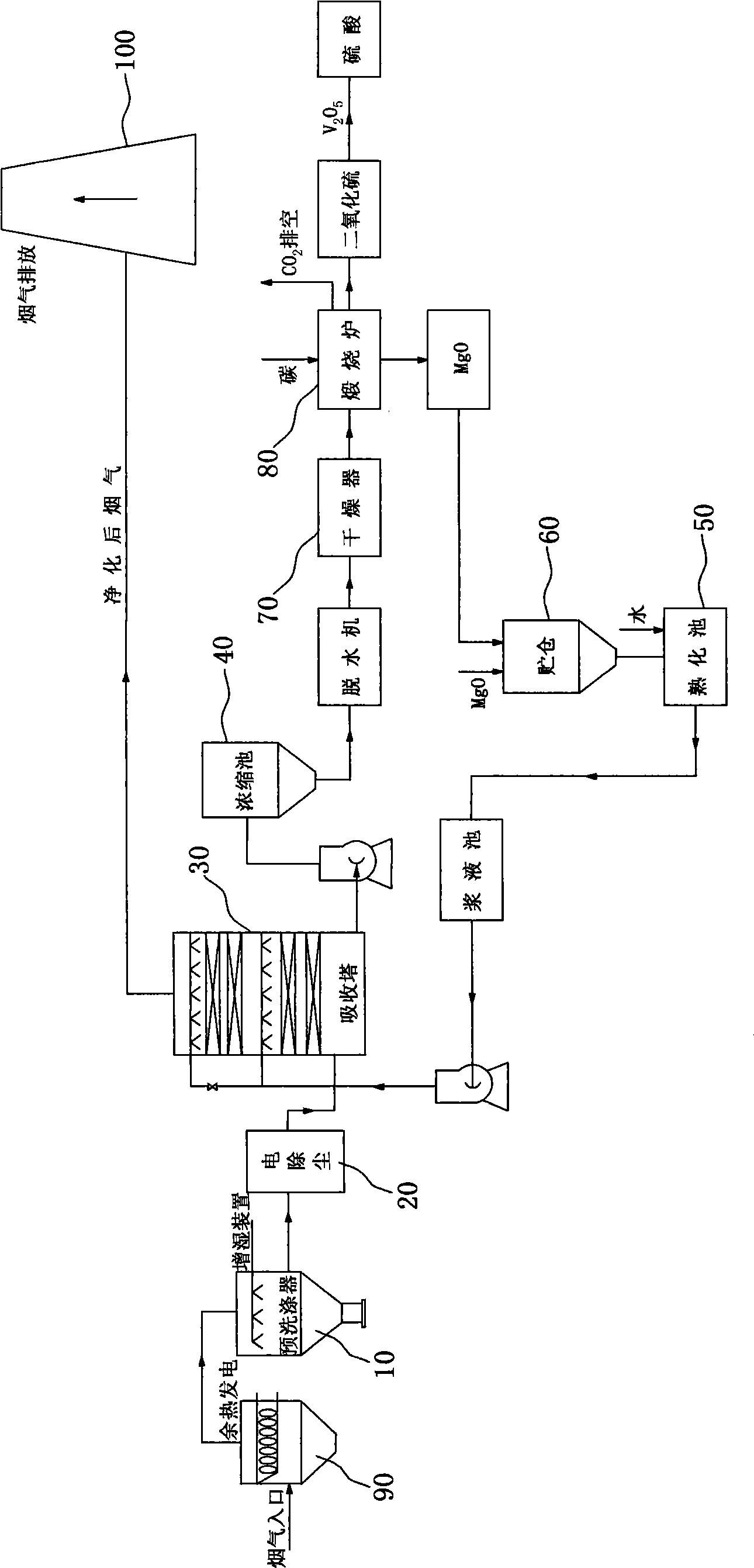
[0015] combine figure 1 , first carry out the pre-dust removal process: in order to prevent the fly ash in the flue gas from entering the absorption tower and depositing it into the desulfurization cycle system, so a pre-dust removal device, namely a pre-scrubber 10, is installed in front of the absorption tower 30. The pre-dust removal device can use Venturi washing to pre-treat the flue gas, so that the temperature of the flue gas is lowered, the temperature is increased, and the fly ash is removed, which is beneficial to the subsequent absorption reaction.

[0016] SO 2 Absorption: In the absorption tower, the flue gas is in contact with the circulating slurry, SO 2 Reacts with absorbents to be removed from flue gas.

[0017] Concentration and drying of the slurry: the content of the slurry discharged from the absorption tower is about 10%, firstly through concentration to increase the solid content of the slurry, and then dehydration and drying. Remove solid surface wat...

Embodiment 2

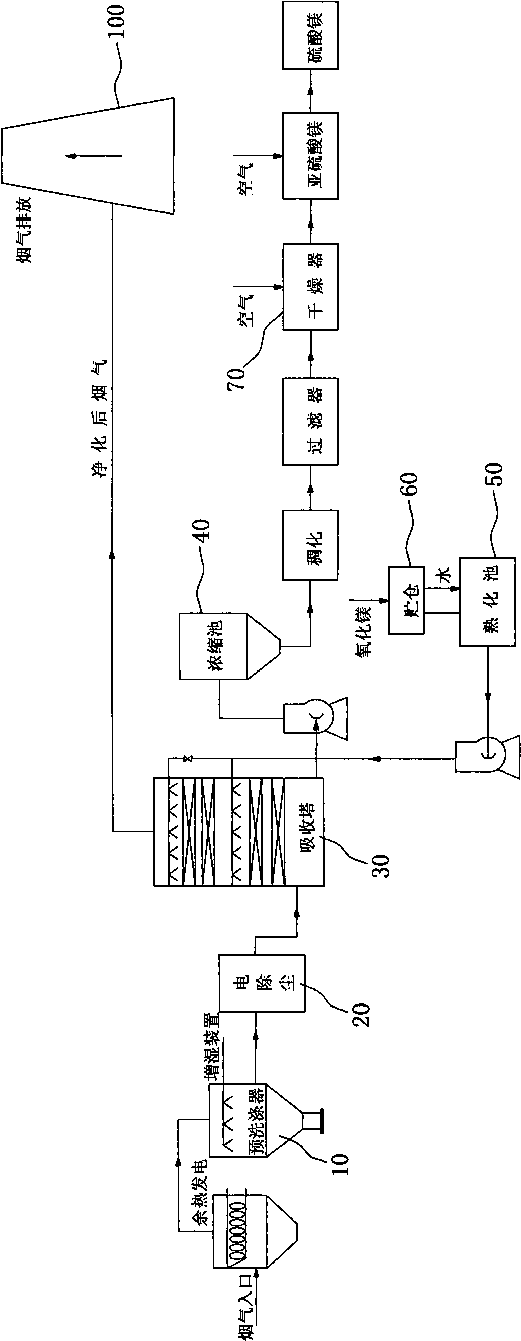
[0022] combine figure 2 , the slurry in the concentration pool 40 is thickened and filtered, and a filter press is used to filter during the dehydration process. Thickening and filtration are all carried out in the concentration pool 40, and the MgSO 3 Fully oxidized with oxygen in the air to obtain commercial magnesium sulfate. Magnesium sulfate can be used as a softener in the paper industry and a compound magnesium fertilizer in the fertilizer industry to improve the yield and quality of crops.

Embodiment 3

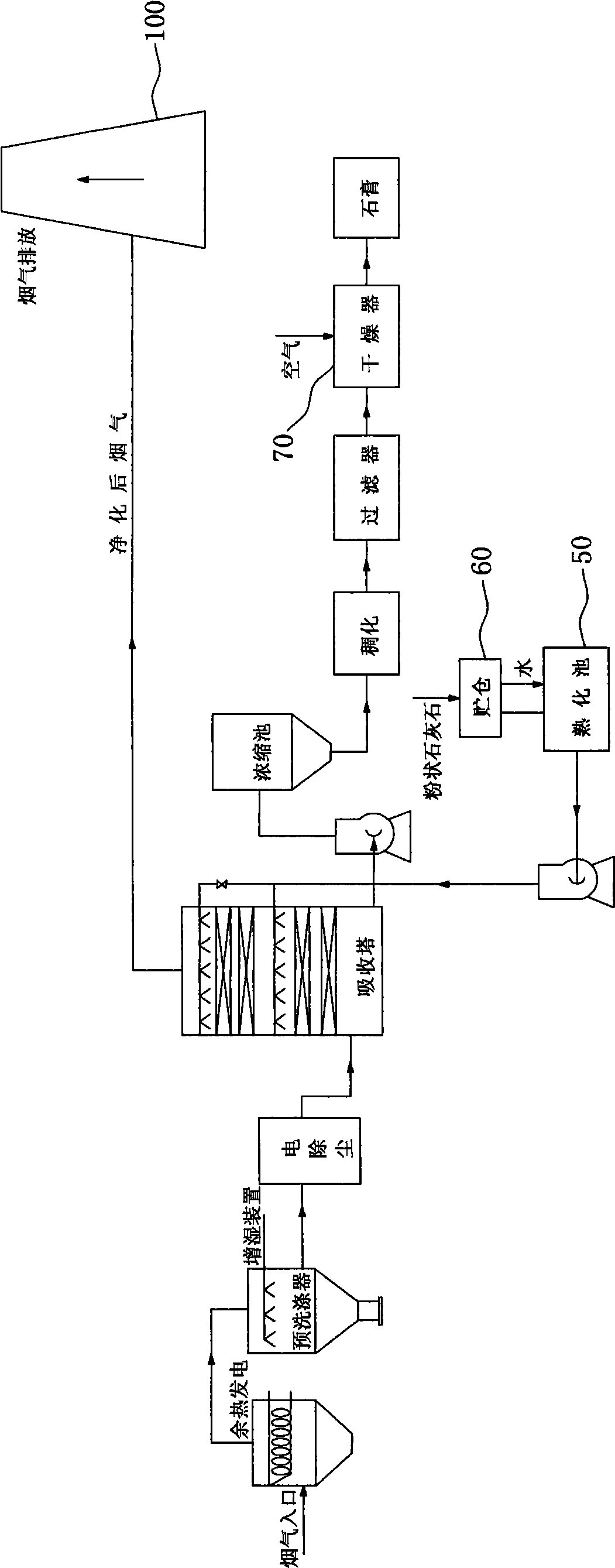
[0024] combine image 3 , put powdery limestone in the storage bin 60 and the aging tank 50, transport it to the absorption tower 30 to absorb the pharynx gas, process the pharynx gas through the concentration tank 40, filter it through a filter after thickening, and then dry it in the drier 70 , get gypsum.


PUM


Abstract

The invention relates to a boiler flue gas desulfurization and dust removal system and energy-saving comprehensive utilization technology, which avoid secondary pollution and resource waste. The boiler flue gas desulfurization and dust removal system comprises a pre-washer for reducing the temperature and increasing the humidity for flue gas, wherein the flue gas after pretreatment and fly ash removal enters an absorption tower, and contacts circulatory serum in the absorption tower, and SO2 in the flue gas reacts with an absorbent so as to be removed from the flue gas; and the flue gas after desulfurization is exhausted out from an exhaust pipe. The SO2 in the flue gas treated by the system reacts with the absorbent so as to be removed from the flue gas; the partial serum can be recycled through aftertreatment; and the flue gas after desulfurization is exhausted out from the exhaust pipe and does not have harm to the environment.

Description

technical field [0001] The invention relates to a boiler flue gas treatment system and energy-saving comprehensive utilization. Background technique [0002] First of all, industrial boilers discharge a large amount of flue gas during operation, and a large amount of heat energy is not fully utilized; at the same time, in the process of dust removal and desulfurization, because the flue gas enters the dust removal system at a certain temperature, the life of various accessories in the dust removal system Short, resulting in increased costs and reduced dust removal efficiency. [0003] In the prior art, a large amount of calcium oxide desulfurizer is used, correspondingly, a large amount of equipment investment is required, the operation cost is high, and the system is easy to scale and cause blockage, and the operation reliability is low. Contents of the invention [0004] The purpose of the present invention is to implement effective treatment of flue gas, and facilitate...

Claims


Application Information

Patent Timeline
Patent Type & Authority Applications(China)
IPC IPC(8): B01D53/80B01D53/50B01D53/96B01D50/00C01B17/74C01F5/40C01F11/46
CPCY02P20/10Y02P20/50
Inventor 徐辉梁燕童翠香钱开如梁运动陈志
Owner ANHUI YUANCHEN ENVIRONMENTAL PROTECTION SCI & TECH
Learn More