Complicate electrode pose pre-adjustment device

A pre-adjustment and electrode technology, which is applied in the field of electrode pose pre-adjustment devices, can solve problems such as long adjustment process time, complex electrode pose pre-adjustment devices, and difficulty in ensuring adjustment accuracy, so as to improve pre-adjustment accuracy and improve processing efficiency , Improve the effect of machining accuracy

Inactive Publication Date: 2009-08-19
HARBIN INST OF TECH
View PDF0 Cites 6 Cited by
  • Summary
  • Abstract
  • Description
  • Claims
  • Application Information

AI Technical Summary

Problems solved by technology

[0003] The purpose of the present invention is to solve the problem that the existing electrode posture adjustment is mainly performed on-site on the electric discharge machining machine tool, and the dial gauge is manually ope

Method used


Image

  • Complicate electrode pose pre-adjustment device
  • Complicate electrode pose pre-adjustment device
  • Complicate electrode pose pre-adjustment device

Examples


specific Embodiment approach 1

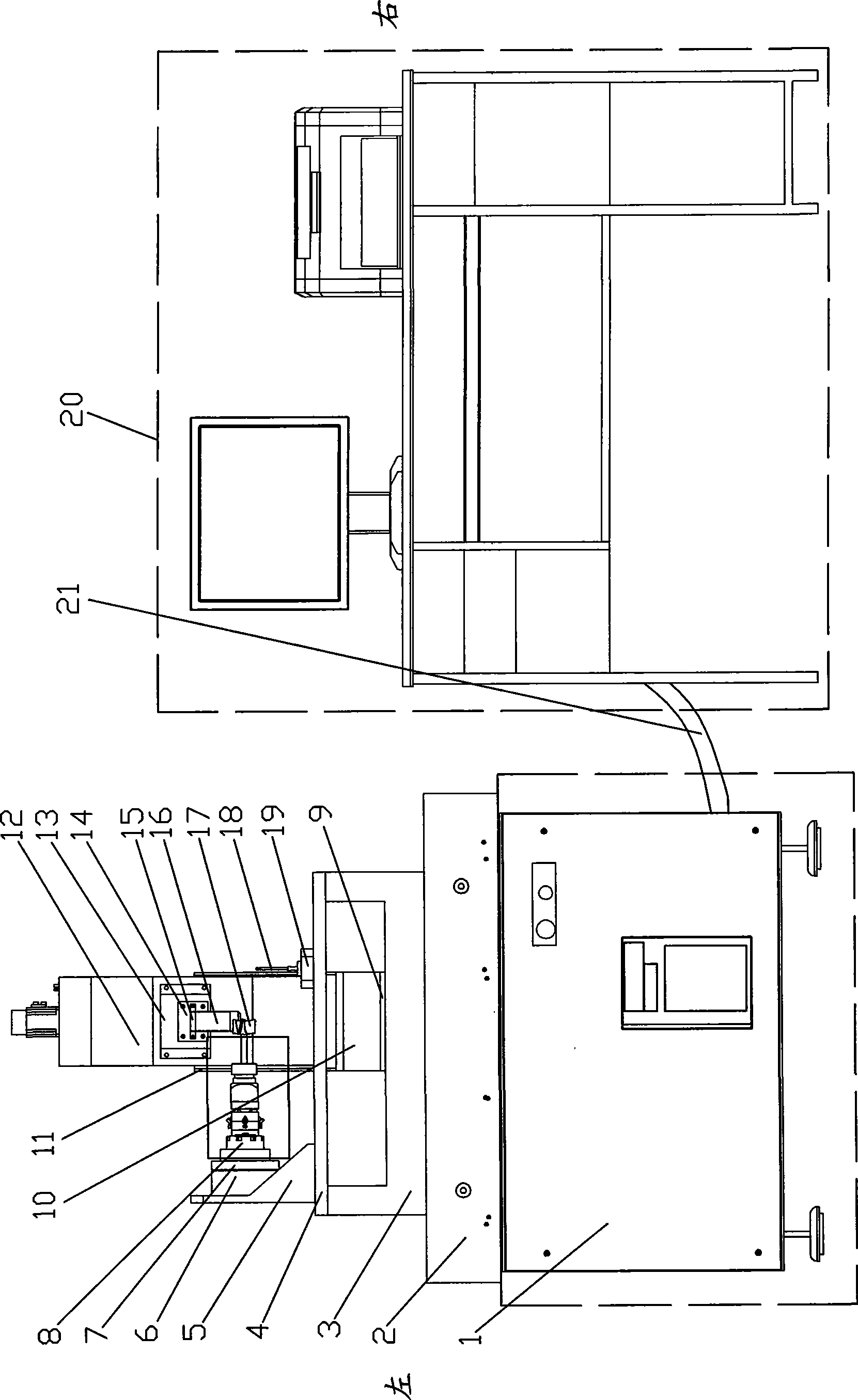
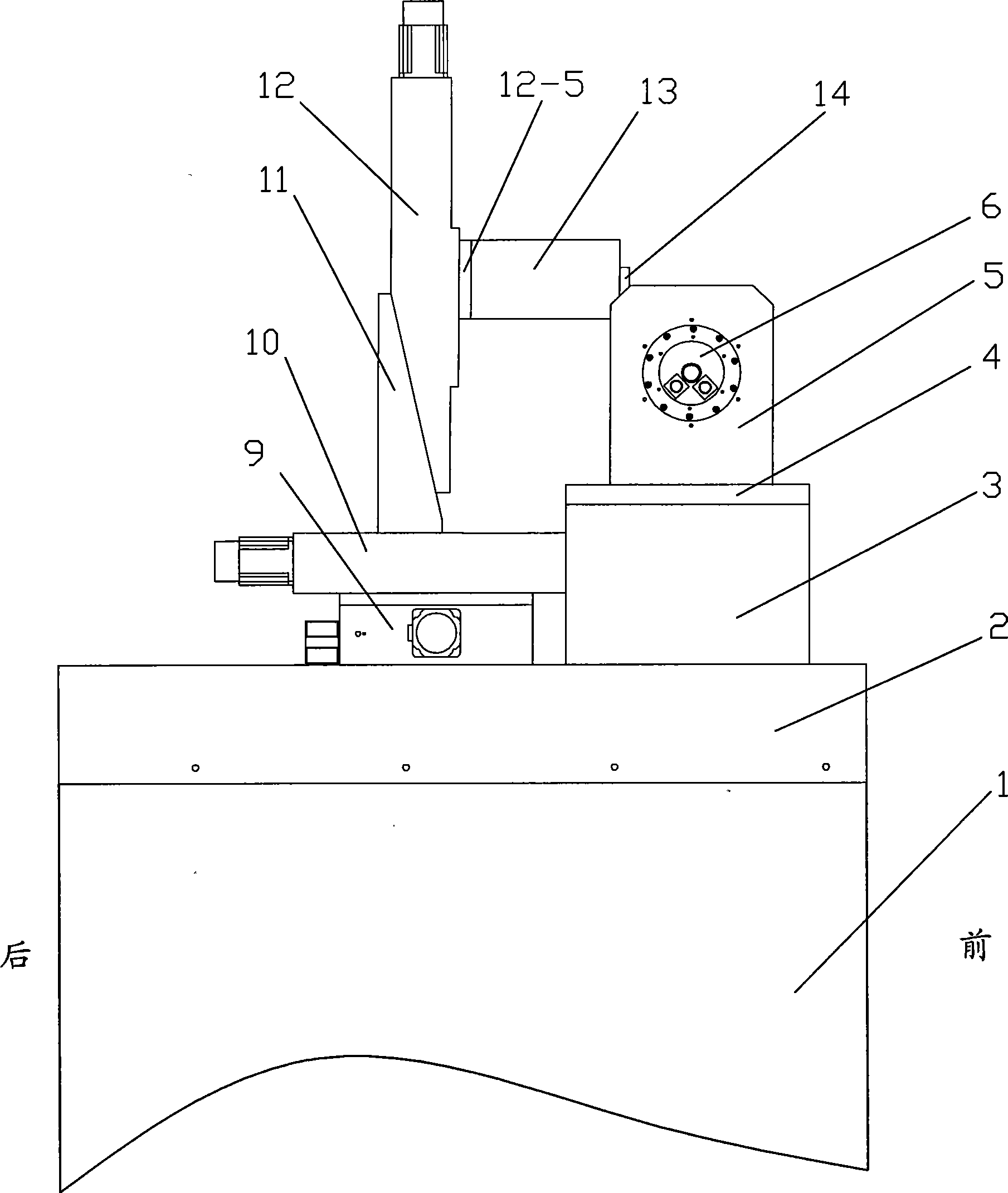
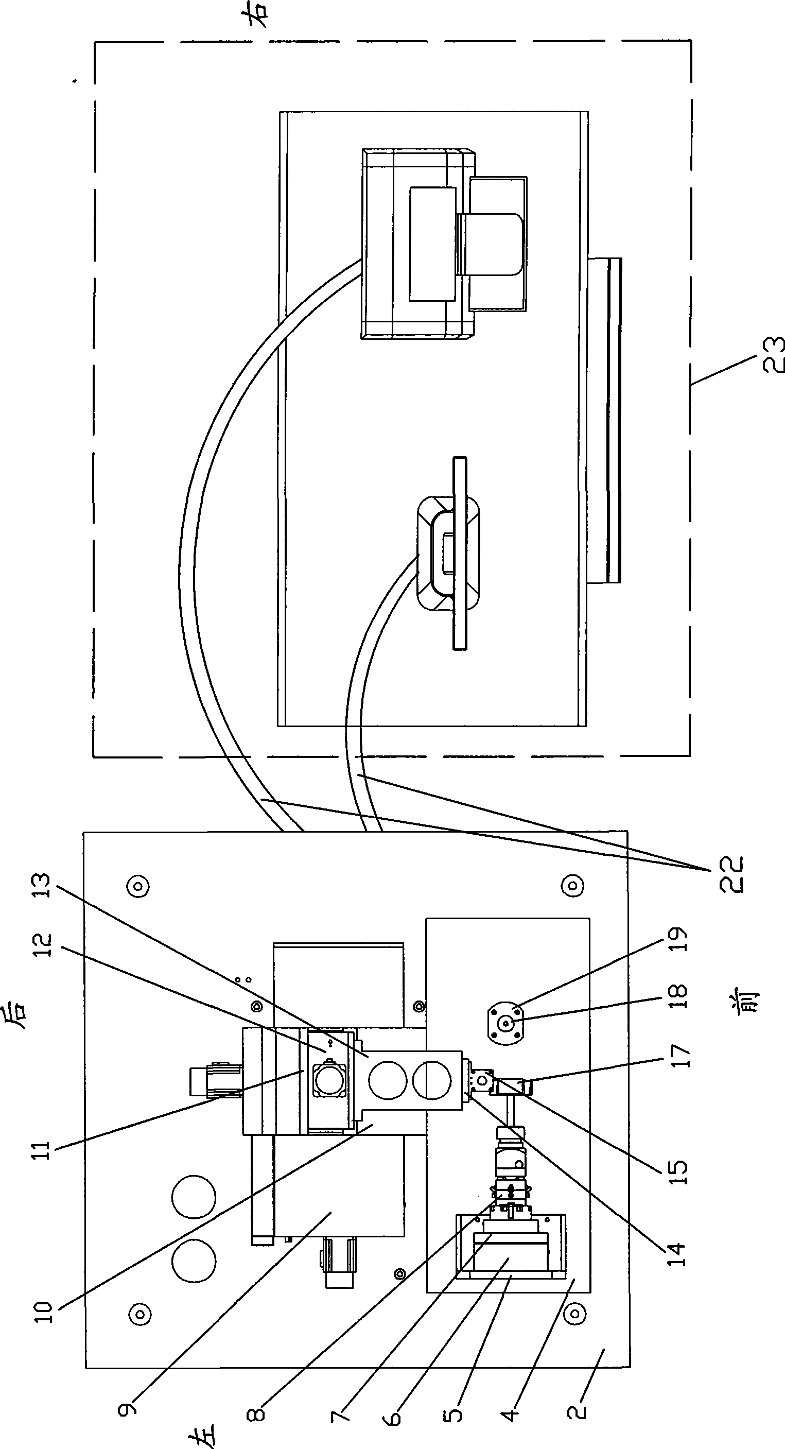
[0007] Specific implementation mode one: combine Figure 1 ~ Figure 3 Describe this embodiment. This embodiment includes an electric control cabinet 1, a large platform 2, a U-shaped mounting base 3, a small platform 4, a mounting base 5, a motor 6, an insulating plate 7, a posture adjustment assembly 8, a left and right moving mechanism 9, a front and rear Moving mechanism 10, up and down moving mechanism 12, extension frame 13, insulating plate 14, measuring head mounting seat 15, measuring head 16, standard ball 18, connecting seat 19, human-computer interaction equipment 20 and cables 21, large platform 2 through the connecting piece Installed on the table of the electric control cabinet 1, the U-shaped mounting base 3 is installed on the large platform 2 through the connecting piece, the small platform 4 is installed on the upper end surface of the U-shaped mounting base 3 through the connecting piece, and the motor mounting base 5 is installed through the connecting piece...

specific Embodiment approach 2

[0008] Specific implementation mode two: combination Figure 4 and Figure 5 Describe this embodiment, the posture adjustment assembly 8 of this embodiment is composed of a connecting chuck 8-1, a slot spring 8-2, a displacement adjustment plate 8-3, an angle adjustment plate 8-4, a swing plate 8-5, and a spring Chuck body 8-6, lock nut 8-7, grinding electrode rod 8-8, two angle adjustment screws 8-9 and two displacement adjustment screws 8-10, connected with chuck 8-1, card slot The shrapnel 8-2, the displacement adjustment plate 8-3 and the angle adjustment plate 8-4 are connected sequentially from left to right, and the left end of the swing plate 8-5 is provided with a conical surface 8-5-1 and the conical surface 8-5-1 Connect the right end of the angle adjustment plate 8-4 through the connecting piece, the right end of the swing plate 8-5 is connected with the left end of the collet body 8-6, and the lock nut 8-7 is set on the grinding electrode rod 8-8. The left end o...

specific Embodiment approach 3

[0009] Specific implementation mode three: combination Figure 6 Describe this embodiment, the left and right moving mechanism 9 of this embodiment is made up of first bottom plate 9-1, two first supporting blocks 9-2, first lead screw 9-3, first lead screw nut 9-4, first The slider 9-5, the first shaft coupling 9-6, the first mounting seat 9-7 and the first motor 9-8 are composed of two first supporting blocks 9-2 fixedly mounted on the first bottom plate 9-1 respectively. On the upper end face of the first lead screw 9-3, the two ends of the first lead screw 9-3 are respectively hinged in the two first support blocks 9-2 and the input end is connected with the output end of the first coupling 9-6, and the first coupling The input end of 9-6 is connected with the output end of the first motor 9-8, and the first motor 9-8 is fixed on the first base plate 9-1 by the first mount 9-7, and the first slide block 9-5 Fixedly mounted on the top of the first leading screw nut 9-4, th...


PUM


Abstract

The invention relates to an electrode pose pre-adjusting device, which aims to solve the problems that the prior electrode pose adjustment is mainly performed in the place of an electric spark machine tool, the adjustment time is long by observing pointer jump of a dial indicator, and the adjustment accuracy is difficultly guaranteed. A first bottom plate is arranged on the table top of a big platform; a second bottom plate is arranged on a first slide block; a support plate is connected with a second slide block on a front and back moving mechanism; an extension support is arranged on the lateral end face of a third slide block; an insulating board is arranged on the front of the extension support; a measuring head mounting seat is arranged on the front of the insulating board; a measuring head is arranged on the front of the measuring head mounting seat; a master ball is fixedly arranged on the upper end face of a small platform; and a human-computer interaction device is connected with an electric control cabinet through a cable. In the process of processing rimed turbine blisks by the electric spark machine tool, the electrode pose pre-adjusting device can synchronously complete adjustment of the electrode pose, so that the processing and the adjustment are performed simultaneously, service working time of the electric spark machine tool is reduced and the processing efficiency of the electric spark machine tool is improved.

Description

technical field [0001] The invention relates to an electrode posture pre-adjustment device. Background technique [0002] In the EDM process of crowned integral turbine disk, the position and orientation adjustment of the forming electrode directly affects the qualified rate and processing efficiency of the product. At present, the posture adjustment of the forming electrode is mainly on-site adjustment, that is, the forming electrode is installed on the EDM machine tool, and the dial indicator is used for adjustment. The operator controls the EDM machine tool table to move back and forth, and observes the dial indicator The pointer jumps, and then judges how to further correct the pose of the electrode. The entire adjustment process occupies most of the auxiliary processing time, so the standby time is long and the efficiency is very low. Contents of the invention [0003] The purpose of the present invention is to solve the problem that the existing electrode posture a...

Claims


Application Information

Patent Timeline
IPC IPC(8): B23H7/26
Inventor 王振龙李茂盛孟凡新迟关心陈济轮王玉魁杭观荣
Owner HARBIN INST OF TECH
Why Eureka
Try Eureka