Turbine shaft engine

A turboshaft engine and generator technology, applied in the direction of machines/engines, gas turbine devices, mechanical equipment, etc., can solve the problems of high energy consumption, poor acceleration performance, etc., to solve the problems of poor acceleration and low speed fuel consumption, comfortable maintenance, easy maintenance effect

Inactive Publication Date: 2009-08-19
严政
View PDF0 Cites 14 Cited by
  • Summary
  • Abstract
  • Description
  • Claims
  • Application Information

AI Technical Summary

Problems solved by technology

[0019] The purpose of the present invention is to provide an improved turboshaft engine, which can solve the problems of poor acceleration performance and high energy consumption at low speeds, so as to adapt to the operating characteristics of automobiles, trains and other transportation tools, so that this turboshaft engine can Applied to vehicles, trains and other means of transportation, giving full play to its own advantages, bringing the benefits of energy saving, environmental protection, comfort and easy maintenance to the above means of transportation

Method used


Image

  • Turbine shaft engine
  • Turbine shaft engine
  • Turbine shaft engine

Examples


Embodiment Construction

[0029] The present invention will be further described below in combination with specific embodiments and accompanying drawings.

[0030] Before explaining the present invention, the existing turboshaft engine is briefly introduced, and its inability to be applied to vehicles such as automobiles and trains is analyzed.

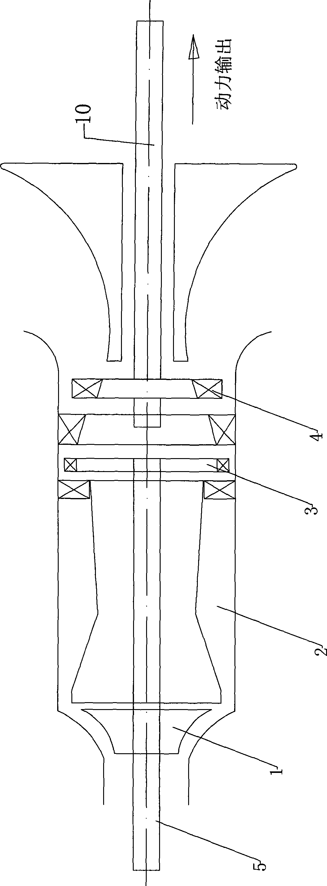
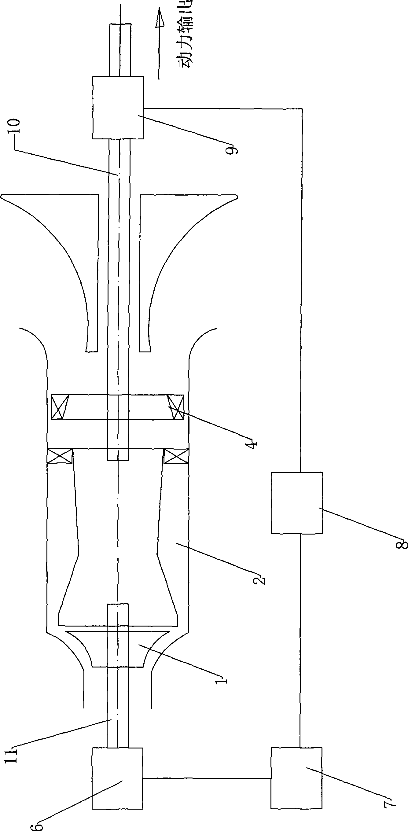
[0031] like figure 1 Shown is the structural diagram of the existing turboshaft engine. It includes a compressor 1 arranged in the casing, a combustion chamber 2 located in the middle of the casing, and a drive turbine 3 located on the right side of the combustion chamber 2 and connected to the compressor 1 through a turbine shaft 5 in rotation. The rotational connection in this specification refers to two or connections that can be rotated synchronously. The right side of the drive turbine 3 is provided with a power turbine 4 (also referred to as "free turbine") for outputting power. The power turbine 4 is rotatably connected with the power shaft 10, and th...


PUM


Abstract

The invention discloses a turboshaft engine which can be used for automobile, train and other means of transportation, aims at resolving the problem that the existing turboshaft engine can not be used for automobiles and trains, and comprises a gas compressor, a combustion chamber and a power turbo; the engine also comprises a gas compressing motor, an electricity generator, a gas compressor shaft and a power shaft; the gas compressor is rotationally connect with the gas compressing motor by the gas compressor shaft, the power turbo is rotationally connect with the electricity generator by the power shaft, the gas compressor shaft and the power shaft are two separated shafts, and the electric connection is applied between the electricity generator and the gas compressing motor.

Description

technical field [0001] The invention relates to a turboshaft engine, in particular to a turboshaft engine applicable to vehicles, trains and other vehicles. Background technique [0002] The turboshaft engine, a type of gas engine, is relatively new to the category of turbine engines with compressors, but has found widespread use in helicopters and VTOL aircraft. [0003] The turboshaft engine began to be installed on the helicopter in December 1951, making the first flight. At that time it belonged to the turboprop engine and did not have a self-contained system. Later, as the use of helicopters in the military and national economy became more and more common, the turboshaft engine gained an independent status. [0004] In operation and construction, the turboshaft engine is closely related to the turboprop engine. They are all evolved from the principle of the turbofan engine, except that the latter turns the fan into a propeller, while the former turns the fan into a h...

Claims


Application Information

Patent Timeline
Patent Type & Authority Applications(China)
IPC IPC(8): F02C6/00F02C7/00F02C9/16
CPCF02C3/103Y02T50/671F02C6/20Y02T50/60
Inventor 严政
Owner 严政
Why Eureka
Try Eureka