Numerical control gear shaping error compensation and gear profile modification method

A processing error and error compensation technology, applied in the field of CNC gear shaping, can solve the problems that the system cannot perform compensation, does not have the ability to adjust the instantaneous transmission ratio, and cannot use standard tool tooth profile modification processing, etc., and achieves easy operation and precision cost. Low, the effect of maintaining machining accuracy

Inactive Publication Date: 2009-09-02
宜昌长机科技有限责任公司
View PDF0 Cites 29 Cited by
  • Summary
  • Abstract
  • Description
  • Claims
  • Application Information

AI Technical Summary

Problems solved by technology
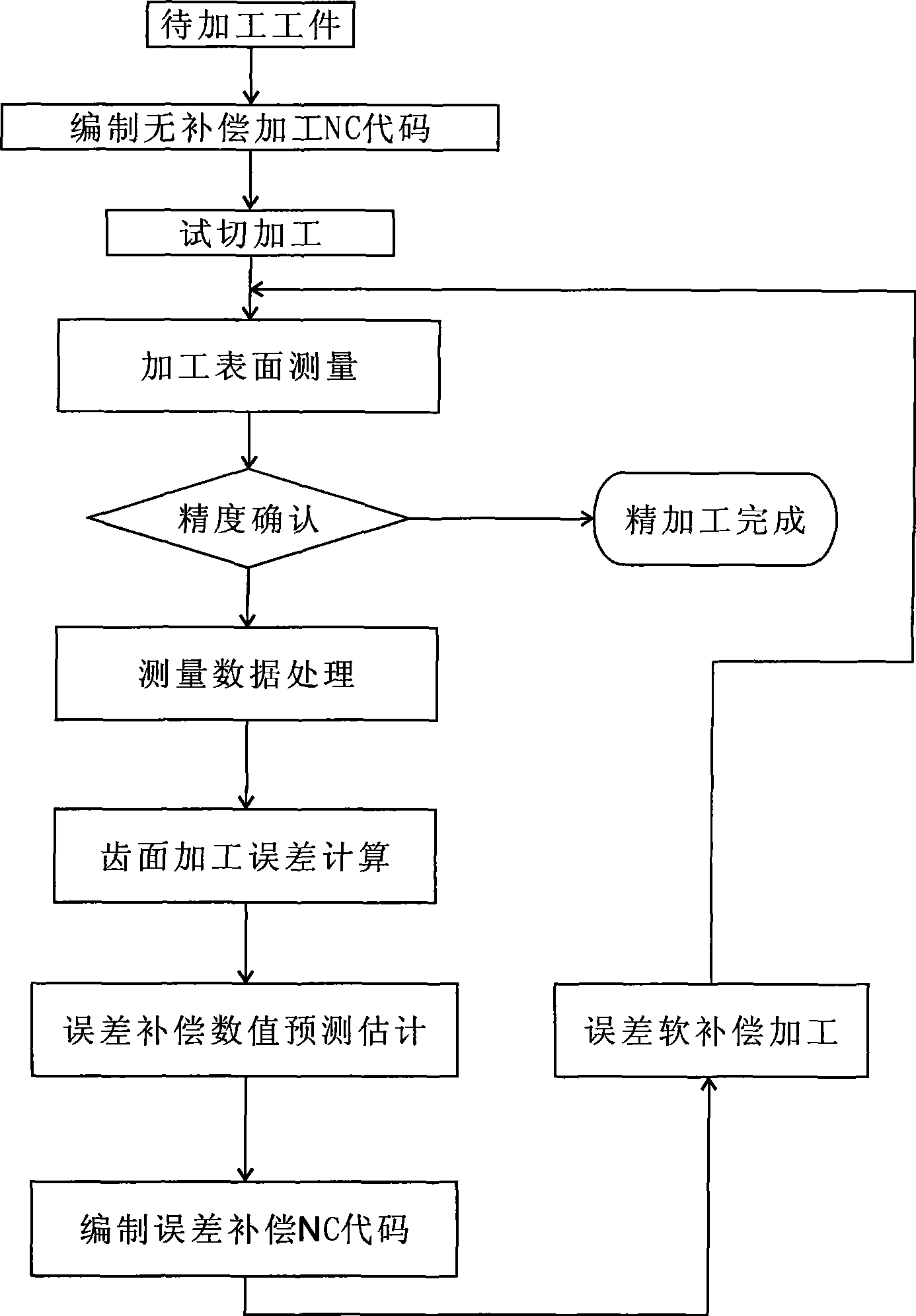
However, CNC gear shaping machines usually only set the generating motion speed ratio, and do not have the function of adjusting the instantaneous transmission ratio between the gear shaping...

Method used


Image

  • Numerical control gear shaping error compensation and gear profile modification method
  • Numerical control gear shaping error compensation and gear profile modification method
  • Numerical control gear shaping error compensation and gear profile modification method

Examples


Embodiment 1

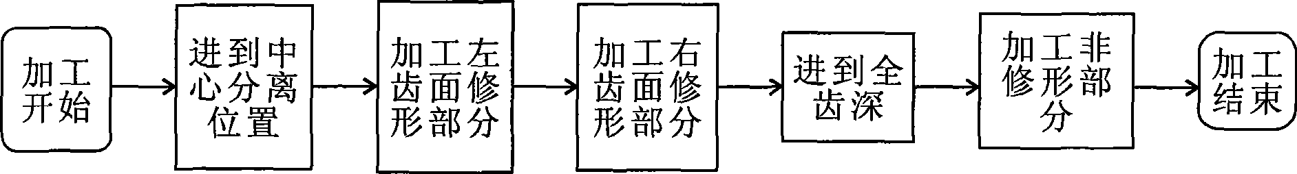
[0044] Embodiment 1: gear shape modification.

[0045] Number of gear teeth z 1 =16, number of gear teeth to be machined z 2 =28, modulus m n =6, pressure angle α=20°, addendum height coefficient h of gear shaper cutter a =1.3, there are three sets of modification curves in total, which are circular arc, straight line and parabola, and the modification amount Δ max =40μm, modification length h max = 4 mm. Take 15 model value points in the arc modification part of the processed gear, and solve the motion according to the principle of digital conjugate surface, and obtain the discrete points of the processed gear, the conjugate points on the gear shaper cutter, and the motion parameters. Use the calculated motion parameters to compile NC machining codes, output the codes, and perform NC machining. The measurement shows that the processing result meets the accuracy requirement of the modification curve.

[0046] Error Analysis of Arc Modification Unit μm

[0047] ...

Embodiment 2

[0048] Embodiment 2: Tooth profile error compensation.

[0049]The processing is carried out on the YKS5132 three-axis CNC gear shaping machine, and the measurement is carried out on the SP-60 involute tooth profile measuring instrument. The parameters of the processed gear are: number of teeth z=28, modulus m=8, pressure angle α=20°, addendum height coefficient h a = 1.0. Firstly, the standard CNC machining program is used for trial cutting, and the tooth profile of the gear to be cut is measured with an involute tooth profile measuring instrument. Points are collected from the measured tooth profile error curve to obtain the tooth profile error of a series of points on the tooth profile, and a new digital virtual tooth profile after error pre-compensation is constructed. Based on this virtual tooth profile, the conjugate motion is solved, and the NC code is compiled for compensation processing. The measurement shows that the machining accuracy has been improved from 8 gra...

Embodiment 3

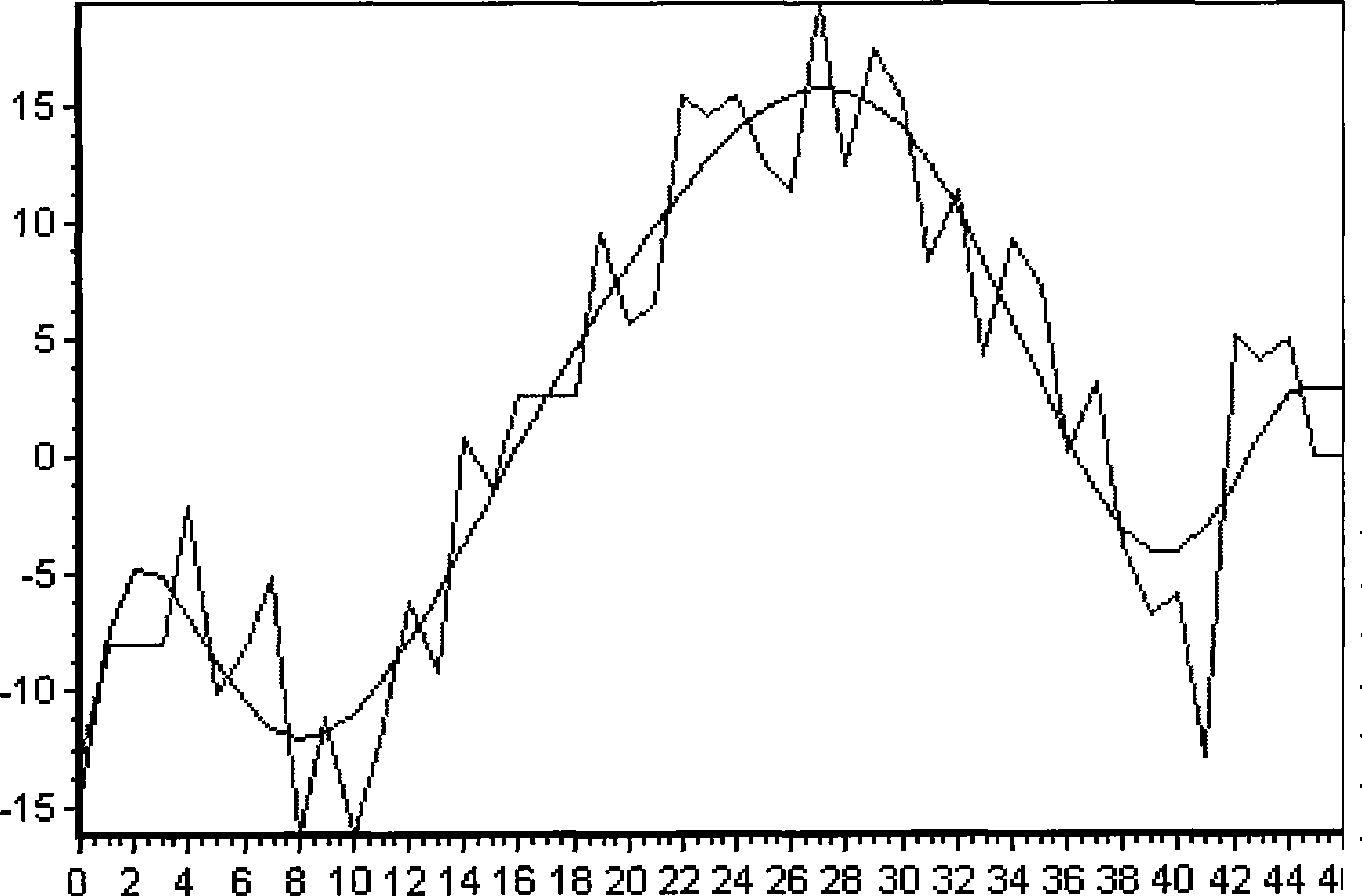
[0050] Embodiment 3: Compensation for tooth pitch accumulative error.

[0051] Gear parameters: m=8, z=28, α=20°, processed on a YKS5132 CNC gear shaping machine. Using the error compensation system can increase the pitch error and cumulative error of the processed gear from 7 levels before compensation to 5~6 levels after compensation, improve the accuracy by more than 1 level, and the compensation effect is obvious.

[0052] Such as image 3 In, uncompensated cumulative data, suprasegmental deviation = 18.0 μm, subsegmental deviation = -11.3 μm, accumulation = 34.3 μm. Such as Figure 4 Among them, the accumulated data after compensation, the above-segment deviation = 16.2 μm, the below-segment deviation = -10.6 μm, and the accumulation = 16.3 μm.


PUM


Abstract

The invention discloses a numerical control gear shaping error compensation and gear profile modification method. The profile error compensation, the pitch error compensation, the tooth pitch accumulative error compensation and the integer accumulative error compensation numerical control processing codes or the profile modification processing code are generated automatically through software, a gear shaper cutter and a workpiece are controlled via a numerical control system so as not to rotate at a speed strictly, and according to the requirement of the compensation procedure, the instantaneous transmission ratio of the gear shaper cutter to the workpiece is adjusted in real time, and the machining precision of the workpiece can be improved by one to two grades on the premise that the precision of the gear shaper cutter and the transmission accuracy of the machine tool are not improved. Especially, when the structural accuracy of the machine tool is naturally lowered after years of use, the accuracy life of the machine tool can be prolonged by using the provided method.

Description

technical field [0001] The invention relates to a method for CNC gear shaping processing, in particular to a method for CNC gear shaping processing error compensation and tooth profile modification Background technique [0002] Fully mechanical gear shaping processing, relying on the configuration of the hanging wheel to generate motion. The CNC gear shaping method uses the controllability of the CNC motion to realize generating motion by separately driving the gear shaping cutter and the worktable, which has the characteristics of high processing flexibility and short transmission chain. However, CNC gear shaping machines usually only set the generating motion speed ratio, and do not have the function of adjusting the instantaneous transmission ratio between the gear shaping cutter and the table movement. The cumulative error and the cumulative error of the whole week cannot be compensated by the system. It is also impossible to use standard tools for tooth profile modifi...

Claims


Application Information

Patent Timeline
IPC IPC(8): B23F1/04
Inventor 易传云钟瑞龄曹祥敖曾照勇
Owner 宜昌长机科技有限责任公司
Why Eureka
Try Eureka