Powder burning furnace

A combustion furnace and powder technology, applied in the field of preparation of spherical silicon micropowder particles, can solve the problems of narrow particle size distribution, inability to uniformly disperse silicon micropowder particles, particle bonding, etc., and achieve high filling rate, simple structure and high fluidity Effect

Inactive Publication Date: 2009-09-02
赵娟
View PDF2 Cites 3 Cited by
  • Summary
  • Abstract
  • Description
  • Claims
  • Application Information

AI Technical Summary

Problems solved by technology

The burner is the most critical equipment in the whole process. In actual production, there are often various problems in the burner and the entire combustion device, such as the feeding method cannot make all the quartz particles enter the flame range, the quartz particles stick to the wall after melting, and the gas And many factors such as the flow direction and injection mode of the combustion-supporting gas, the degree of dispersion of the material will affect the product quality
[0004] When Japanese Patent Laid-Open No. 9-89224 is used to manufacture spherical silicon micropowder, the particles of silicon micropowder cannot be uniformly dispersed, and the particles are bonded to each other, reducing the spheroidization rate.
Moreover, the particle size distribution is too narrow, and the fluidity is poor when used as a filler for epoxy resin
[0005] The spheroidizing furnace proposed in Japanese Patent Laid-Open No. 10-85577 uses circular holes to supplement cold air along the spheroidizing furnace wall. Although it has the effect of preventing the molten powder from adhering to the inner wall of the furnace, if the amount of air entering is too large, it will cause the spheroidizing furnace to If the temperature is too low, the spheroidization rate of silica powder will be reduced

Method used


Image

  • Powder burning furnace
  • Powder burning furnace
  • Powder burning furnace

Examples


Embodiment Construction

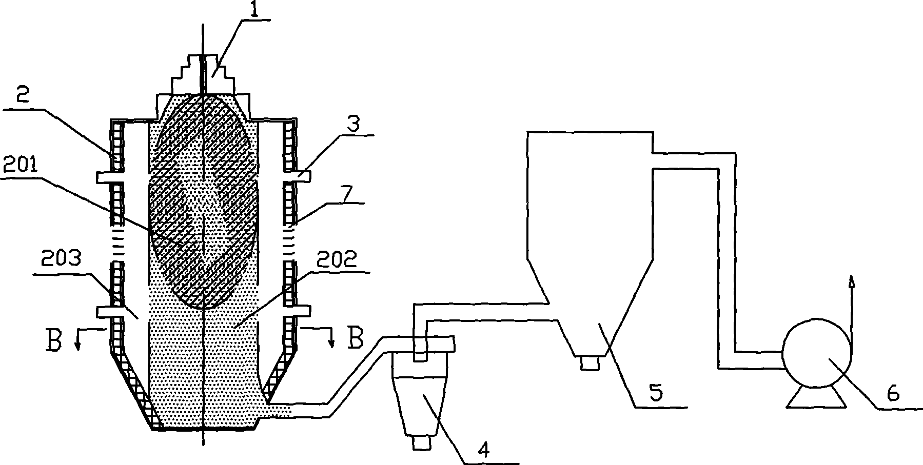
[0020] Such as figure 1 As shown, a powder combustion furnace provided by the present invention includes a burner 1 and a spheroidizing furnace 2, and the bottom of the spheroidizing furnace 2 is sequentially connected to a cyclone separator 4, a bag filter 5, and an induced draft fan 6.

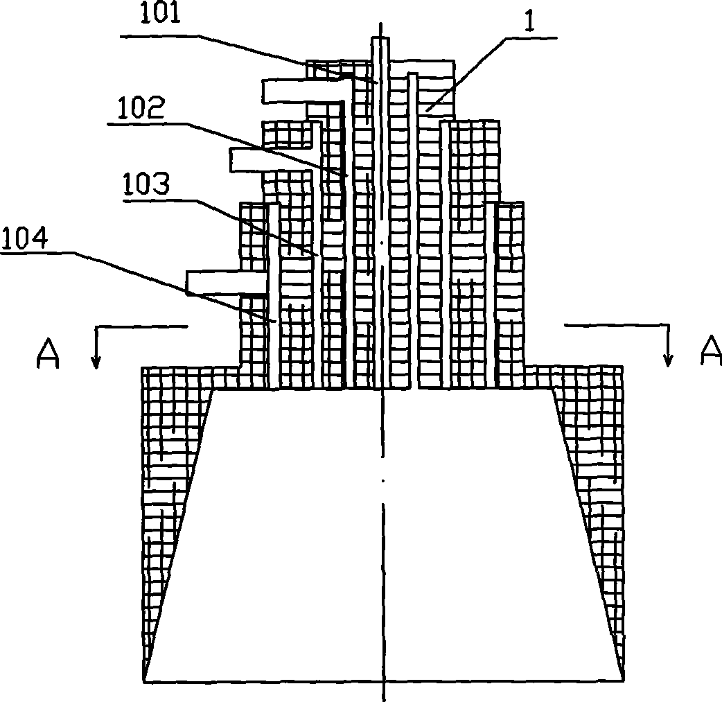
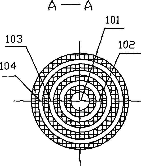
[0021] Such as figure 2 , image 3 As shown, the center of the burner 1 is provided with an inner epoxy central gas injection hole 101, and three layers of annular gas injection channels 102, 103, 104 arranged around the center of the burner.

[0022] Such as figure 1 , Figure 4 As shown, a group of two layers of cooling air inlets 3 are provided on the furnace wall of the spheroidizing furnace 2, and each layer has four cooling air inlets 3, which enter the spheroidizing furnace along the tangential direction of the furnace body.

[0023] The burner 1 is placed on the upper part of the spheroidizing furnace 2 with a vertical cylinder structure, and the center of the burner 1 is provid...


PUM


Abstract

The invention relates to a powder burning furnace which comprises a burner (1) and a spheroidizing furnace and is characterized in that the center of the burner (1) is provided with a gas orifice (101) and three layers of annular gas injection passages (102, 103 and 104). Inorganic powder and oxygen are injected from the gas orifice (101) after being mixed and mixedly burnt in a burning chamber together with natural gas and oxygen which are injected from the annular gas injection passages (102, 103 and 104). The invention has the advantages that the outer layer of annular protective oxygen can effectively protect powdery granules from sticking a fire wall and ensure oxygen rich burning, and spherical silica micro powder with excellent performances such as high dielectric property and filing ratio, low expansion and stress, high liquidity, and the like can be used, thereby the powder burning furnace can be applied to basal plates and packaged materials of large-scale and super large-scale integrated circuits.

Description

technical field [0001] The invention belongs to a powder burning device, which is mainly used for the preparation of non-metallic mineral powder, especially spherical silicon micropowder particles. Background technique [0002] The rapid development of the electronic information industry has led to the continuous expansion of the integrated circuit market, and silicon micropowder as a filling material for epoxy molding compound for integrated circuit packaging has also shown broad development prospects, but the quality requirements for silicon micropowder are also increasing. In addition to the requirements of ultra-fine, high-purity, and low-radioactive element content, special requirements for spheroidization are also proposed for the particle shape. As a filler for epoxy molding compound, spherical silica powder can significantly improve the filling rate and fluidity compared with angular silica powder. It has become a reality to replace angular silica powder with spheric...

Claims


Application Information

Patent Timeline
Patent Type & Authority Applications(China)
IPC IPC(8): C01B33/18
Inventor 赵娟
Owner 赵娟
Why Eureka
Try Eureka