Unlock instant, AI-driven research and patent intelligence for your innovation.

Device and method for limiting short-circuit current

A technology of short-circuit current limitation and current transformer, which is applied in circuit devices, emergency protection circuit devices, emergency protection circuit devices for limiting overcurrent/overvoltage, etc., and can solve the problem of overvoltage in power systems, large capacitor banks, Problems such as high equipment cost, achieve the effect of increasing short-circuit current value, reducing arc extinguishing time, and reducing manufacturing cost

Inactive Publication Date: 2010-12-15
STATE GRID CORP OF CHINA +3
View PDF4 Cites 0 Cited by
  • Summary
  • Abstract
  • Description
  • Claims
  • Application Information

AI Technical Summary

Problems solved by technology

The disadvantages of the current limiter made of superconducting materials are: complex mechanism, high price, immature technology of superconducting materials, heat dissipation when superconducting materials present large resistance
The shortcomings of the current limiter formed by the principle of series resonance are: the capacitor bank is large in size, large in area, difficult to operate and maintain, expensive, overvoltage in the power system caused by series resonance, and short-circuit current resistance of the valve thyristor
The disadvantages of the existing magnetically saturated reactor current limiter are: the circuit for supplying DC current to the DC coil is complicated; the corresponding equipment has high technical requirements; the equipment is bulky and the equipment cost is high; etc.
[0007] The main purpose of existing current limiters is to limit the amplitude of large currents. Therefore, there is a current situation of large equipment volume and high equipment cost.

Method used


Image

  • Device and method for limiting short-circuit current
  • Device and method for limiting short-circuit current
  • Device and method for limiting short-circuit current

Examples


Embodiment Construction

[0035] The present invention will be further described below in conjunction with the accompanying drawings and embodiments.

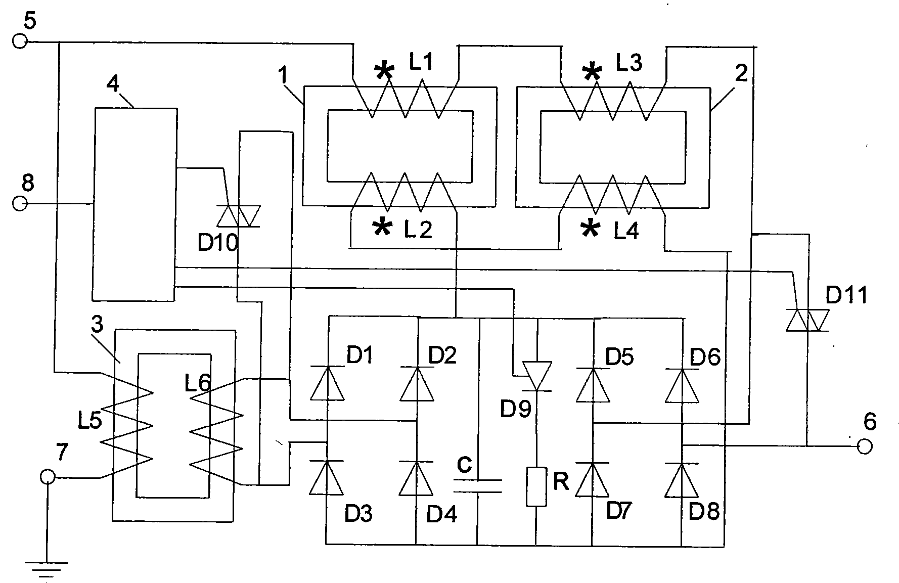
[0036] The structure and connection method of the short-circuit current limiting device are as follows: figure 1shown. The device is connected in series to the transmission line, the input terminal 5 is connected to the circuit breaker, the output terminal 6 is connected to the transmission circuit, and the grounding terminal 7 is grounded. When the power system is running normally, the circuit breaker is closed, and the short-circuit current limiting device obtains the transmission circuit voltage. One end of the primary winding L5 of the current transformer 3 is connected to the input terminal 5, and the other end is connected to the ground terminal 7, and the power transmission circuit voltage is sent to the primary winding L5 of the current transformer 3; the secondary winding L6 of the current transformer 3 passes through the diode D1 , D2, D3, D...


PUM


Abstract

The invention discloses a device and a method for limiting short-circuit current. The device and the method reduce the values of the short-circuit current in sections surrounding a zero crossing pointThe invention discloses a device and a method for limiting short-circuit current. The device and the method reduce the values of the short-circuit current in sections surrounding a zero crossing pointanother full bridge rectifier consisting of light-emitting dioxides D5, D6, D7 and D8; a capacitor C; a control circuit; a thyristor D9; two triode bidirectional thyristor switch modules D10 and D14; another full bridge rectifier consisting of light-emitting dioxides D5, D6, D7 and D8; a capacitor C; a control circuit; a thyristor D9; two triode bidirectional thyristor switch modules D10 and D11; and a resistor R.1; and a resistor R.and prolong the time of low-current sections surrounding the zero crossing point, so that the volume and manufacturing cost of the short-circuit current limiting device are reduced and the loss of a and prolong the time of low-current sections surrounding the zero crossing point, so that the volume and manufacturing cost of the short-circuit current limiting device are reduced and the loss of apower system during normal operation is reduced. The structure of the device comprises: magnetically saturable iron-core reactors I and II; a magnetically saturable iron-core reactor coil L1 and a dirpower system during normal operation is reduced. The structure of the device comprises: magnetically saturable iron-core reactors I and II; a magnetically saturable iron-core reactor coil L1 and a direct current coil L2 which arranged on the magnetically saturable iron-core reactor I; a magnetically saturable iron-core reactor coil L3 and a direct current coil L4 which are arranged on the magneticect current coil L2 which arranged on the magnetically saturable iron-core reactor I; a magnetically saturable iron-core reactor coil L3 and a direct current coil L4 which are arranged on the magnetically saturable iron-core reactor II; a current transformer having a primary side winding L5 and a second side winding L6; a full bridge rectifier consisting of light-emitting dioxides D1, D2, D3 and Dally saturable iron-core reactor II; a current transformer having a primary side winding L5 and a second side winding L6; a full bridge rectifier consisting of light-emitting dioxides D1, D2, D3 and D4;

Description

technical field [0001] The invention relates to the field of power transmission and transformation in power systems, in particular to a short-circuit current limiting device and method. Background technique [0002] Electric energy has become an indispensable driving force for industries, agriculture, national defense, transportation and other sectors. With the continuous development of the power system and the continuous increase of power generation capacity, the short circuit current caused by the short circuit of the power system is very large. The short circuit current caused by the short circuit in the power system is very harmful to the power system. Relay protection can automatically cut off the short-circuit current when a short-circuit occurs in the power system. The relay protection device measures whether there is a short circuit in the power system by protecting the electrical quantities sent by the voltage transformer TV and current transformer TA at the insta...

Claims


Application Information

Patent Timeline
IPC IPC(8): H02H9/02H02H3/08
Inventor 李晓明
Owner STATE GRID CORP OF CHINA
Features
  • R&D
  • Intellectual Property
  • Life Sciences
  • Materials
  • Tech Scout
  • Unparalleled Data Quality
  • Higher Quality Content
  • 60% Fewer Hallucinations
Learn More