Bridge type mixing rectification circuit

A technology of mixed rectification and rectification circuit, which is applied to conversion equipment with intermediate conversion to AC, irreversible AC power input conversion to DC power output, etc., which can solve the problems of difficult driving, large diode voltage drop, and low overall efficiency. Achieve the effect of simple and convenient driving circuit, improved device reliability, and reduced number of winding turns

Inactive Publication Date: 2009-09-02
瑞谷科技(深圳)有限公司
View PDF0 Cites 10 Cited by
  • Summary
  • Abstract
  • Description
  • Claims
  • Application Information

AI Technical Summary

Problems solved by technology

(1) The bridge rectifier uses four MOS tubes, which have high efficiency, but there are the following difficulties. First, the driving is more difficult, because there is a floating ground drive, or a transformer is used to drive, but the transformer is large in size. It is not suitable for volume converters
Or use integrated chip drive, but their cost is high, not suitable for low-cost high-power converters
2. There is a two-way flow of energy in synchronous rectification, and the light-load efficiency is low. Due to the reverse flow of energy during normal shutdown, a large negative pressure or back-injection stress will be formed on the output power tube
If the energy of the capacitor on the output side is released directly after shutdown, then a negative pressure will be formed on the output side, which will affect the use of the output device
(2) Four diodes are used for bridge rectification. Although the withstand voltage level of the diode and the loss of the transformer are reduced, the overall efficiency is still low due to the large voltage drop of the high-voltage rectifier diode.

Method used


Image

  • Bridge type mixing rectification circuit
  • Bridge type mixing rectification circuit
  • Bridge type mixing rectification circuit

Examples


Embodiment Construction

[0021] The present invention will be further described below in conjunction with the accompanying drawings and embodiments.

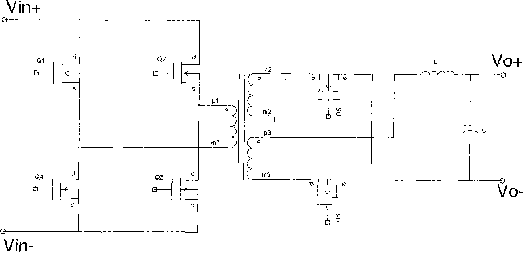
[0022] Such as Figure 4 As shown, it is a circuit diagram of Embodiment 1 of the present invention, and the circuit is used in combination with a hybrid rectifier circuit and a primary-side full-bridge circuit. In ordinary DC / DC converters, especially for medium power converters, in order to improve efficiency, a bridge rectifier circuit is often used on the input side, which is four synchronous rectifier tubes Q1, Q2, Q3, Q4, the four The synchronous rectifier is an N-channel metal oxide semiconductor field effect transistor. The output side includes: two synchronous rectifiers Q5, Q6 and two diodes D1, D2, the above two synchronous rectifiers Q5, Q6 are located at the lower end of the bridge rectifier circuit; the above two diodes D1, D2 are located at the bridge rectifier the upper end of the rectifier circuit.

[0023] The synchronous rectifiers...


PUM


Abstract

The invention relates to a bridge type mixing rectification circuit which is applied to an isolated and non-isolated DC/DC power source. The input side of the bridge type mixing rectification circuit is a double-end normal shock rectification circuit, and the output side is a diode and an MOS tube bridge type mixing rectification circuit. Compared with full-wave rectification, the rectification mode effectively reduces the copper loss of a transformer and greatly lowers a voltage class of a rectifying tube; and compared with full-bridge diode rectification, introduced synchronous rectification also reduces the loss of the rectifying tube. The bridge type mixing rectification circuit maximally enhances the efficiency of a medium-voltage output power source and a high-voltage output source and prevents the two-direction flow under the condition of current component assembly, thereby enhancing the reliability of a system.

Description

technical field [0001] The invention relates to a hybrid rectification circuit, in particular to a bridge type hybrid rectification circuit applied to a DC / DC converter. Background technique [0002] Such as figure 1 As shown, it is an existing common full-bridge plus full-wave synchronous rectification circuit, and the secondary side is a full-wave synchronous rectification circuit. For the secondary side rectifier of this topology, since its withstand voltage level is twice that of the bridge rectifier, and the current forward voltage drop and reverse recovery characteristics of the high-voltage diode cause relatively large losses, reduce the diode withstand voltage level Finally, ordinary Schottky diodes can be used, and the loss can be greatly reduced. Moreover, the number of turns of the transformer winding for full-wave rectification is twice that of the bridge rectifier winding on the secondary side, and the copper loss of the secondary winding of the transformer is...

Claims


Application Information

Patent Timeline
Patent Type & Authority Applications(China)
IPC IPC(8): H02M3/28H02M7/12
Inventor 高保成
Owner 瑞谷科技(深圳)有限公司
Why Eureka
Try Eureka