Optical fiber drawing cooling system

A cooling system and optical fiber technology, which is applied in glass manufacturing equipment, glass production, manufacturing tools, etc., can solve the problems of cooling tube design, high precision requirements for processing difficulty, and increased investment in optical fiber production costs, so as to reduce whiplash and improve cooling Effect, the effect of improving the pass rate

Active Publication Date: 2011-06-08
四川天府江东科技有限公司
View PDF2 Cites 0 Cited by
  • Summary
  • Abstract
  • Description
  • Claims
  • Application Information

AI Technical Summary

Problems solved by technology

The efficiency is high, but the design of the cooling tube, the processing difficulty, and the precision requirements are high, and it involves auxiliary equipment (gas processing device), which greatly increases the cost of optical fiber production.

Method used


Image

  • Optical fiber drawing cooling system
  • Optical fiber drawing cooling system

Examples


Embodiment Construction

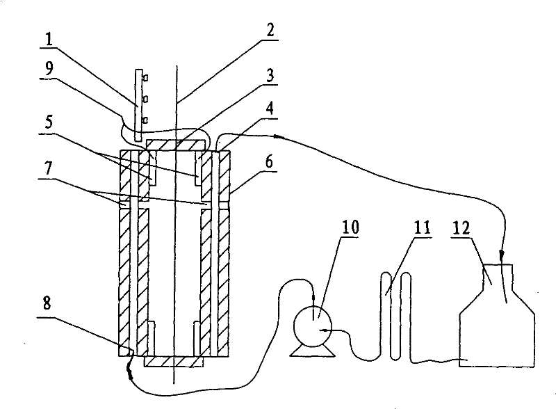
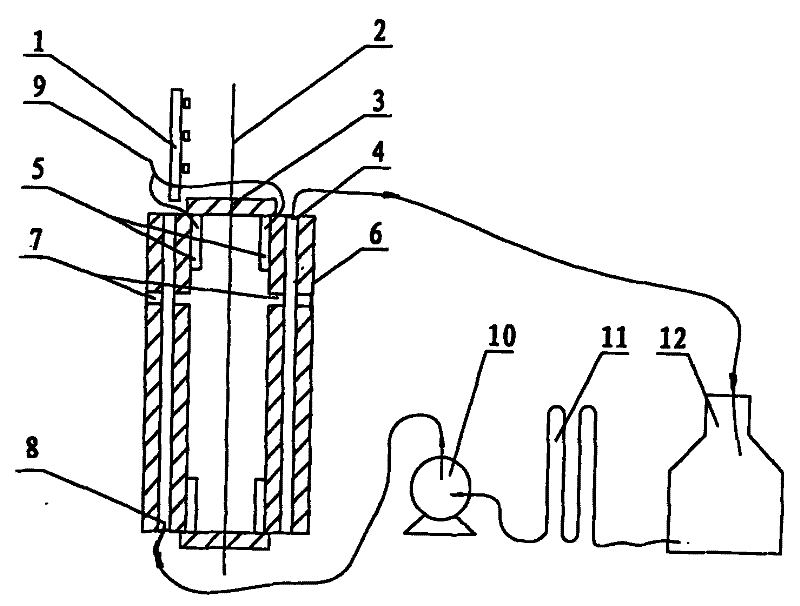
[0018] Refer to attached figure 1 , The optical fiber drawing cooling system is composed of static electricity removal device, cooling pipe body 6, cooling water pipe, gas pipe, cooling water circulation device and so on.

[0019] Static removal device: The static removal device is composed of static eliminator 1 and static transfer parts. Above the cooling pipe body 6, a static eliminator 1 is installed to alternately generate positive and negative ions to eliminate the static electricity generated before the optical fiber enters the cooling pipe body 6; Under normal circumstances, the optical fiber shakes seriously. At this time, the bare optical fiber 2 and the cooling tube body 6 generate static electricity due to contact friction, and the static electricity transfer part collects the generated static electricity and releases it to the ground. The static eliminator adopts the commercially available SFM300 high-performance miniature static eliminator. The static electricit...


PUM

PropertyMeasurementUnit
diameteraaaaaaaaaa
diameteraaaaaaaaaa

Abstract

The invention discloses an optical fiber drawing cooling system, and relates to a bare optical fiber cooling system in a single mode optical fiber drawing process. The optical fiber drawing cooling system is used for reducing the temperature of an optical fiber before coated, is suitable for improving the optical fiber curing performance, and ensures that the single mode optical fiber is applied to an optical fiber communication system with high speed, high capacity and long distance. A structure of the optical fiber drawing cooling system consists of an antistatic device, a cooling tube body, a cooling water pipe, a gas pipeline and a cooling water circulation device, wherein the antistatic device consists of a static eliminator and a static transferring component; the cooling tube body is provided with an inner cavity which is suitable for passing through the optical fiber, and the outside of the inner cavity is provided with the cooling water pipe and a gas injection channel of cooling gas; an upper mouth and a lower mouth of the cooling tube body are provided with drain plugs with variable apertures; the cooling water pipe is arranged on the outside of the inner cavity of the cooling tube body; the cooling water circulation device comprises a cooling water storage tank, a cooling water pump and a refrigerator; and the gas injection channel of the cooling gas is positioned on the lateral part of the cooling tube body, communicated with the inner cavity of the cooling tube body, and is distributed on the periphery of the inner cavity.

Description

technical field [0001] The optical fiber drawing cooling system of the invention relates to a bare fiber cooling system in the single-mode optical fiber drawing process, which is used for reducing the temperature of the optical fiber before coating, and is suitable for improving the curing performance of the optical fiber. An optical fiber drawing cooling system that makes single-mode optical fiber suitable for high-speed, large-capacity, and long-distance optical fiber communication systems. Background technique [0002] In the whole production process of optical fiber, the first step is to melt the optical fiber preform: the optical fiber preform is placed in the heating furnace of the wire drawing device, and after melting into a fluid state, it is cooled, coated and solidified, and then the wire is taken up. , become a semi-finished fiber. When the optical fiber is just out of the furnace, the temperature is high, and the prerequisite for optical fiber coating protectio...

Claims


Application Information

Patent Timeline
Patent Type & Authority Patents(China)
IPC IPC(8): C03B37/027
CPCC03B37/02718Y02P40/57
Inventor 薛济萍薛驰沈一春朱兆章薛群山曹珊珊卢德勇陈娅丽刘明
Owner 四川天府江东科技有限公司
Why Eureka
Try Eureka