Method and device for automatically detecting boundary of beam-limiting device

A technology of automatic detection and beam limiter, which is applied to instruments, instruments for radiological diagnosis, image data processing, etc., can solve the problems of ineffective images, slow operation speed, and complex algorithms, etc., to solve missed detection and false detection Positive issues, ensuring boundary validity, computing simple effects

Inactive Publication Date: 2009-09-23
SHENZHEN MINDRAY BIO MEDICAL ELECTRONICS CO LTD
View PDF0 Cites 36 Cited by
  • Summary
  • Abstract
  • Description
  • Claims
  • Application Information

AI Technical Summary

Problems solved by technology

[0006] From the above introduction, it is not difficult to see that the problems existing in the existing technology are: the algorithm is too complex and the operation speed is slow; the accuracy rate needs to be further improved, for example, the transition boundary between bone and soft tissue may be mistaken for the beam limiter area The boundary of the boundary; it is necessary to have more accurate background pixel threshold information to verify whether each detected boundary line is valid and to verify whether the detected overall beam limiter boundary is valid; for underexposed images with poor contrast, or overexposure images may not be very effective and false positives may occur

Method used


Image

  • Method and device for automatically detecting boundary of beam-limiting device
  • Method and device for automatically detecting boundary of beam-limiting device
  • Method and device for automatically detecting boundary of beam-limiting device

Examples


Embodiment Construction

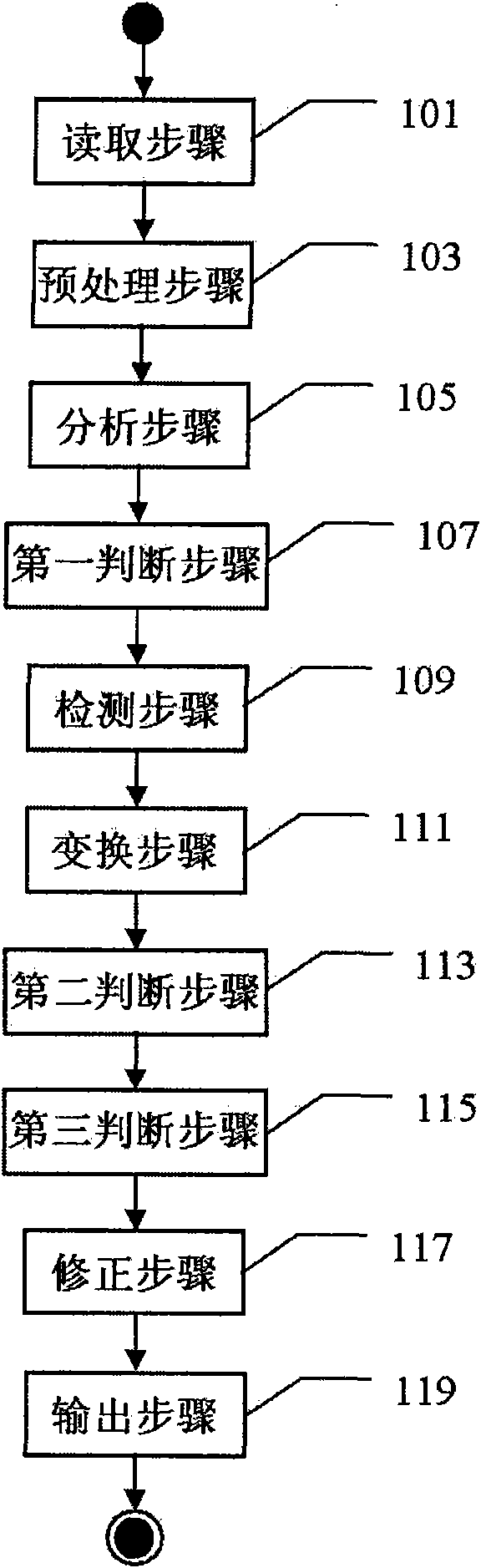
[0043] as attached figure 1 As shown, in addition to the reading step 101 , the detection step 109 and the transformation step 111 , the method for automatically detecting the boundary or region of the beam limiter according to this embodiment may optionally include other steps. In the reading step 101, the original image is read in, the image is acquired by the X-ray imaging system, and the image may have passed simple corrections (such as corrections such as bad pixels, bad lines, and invalid pixel removal) without any image enhancement Technology processing (however, the enhanced image can also be applied to the method of this embodiment). The read-in images may not be pre-processed, or may be pre-processed (step 103), that is, scaled and / or appropriately cut. The purpose of scaling is to speed up the operation and improve the operation speed; appropriate cutting according to the needs can control unnecessary detection at all.

[0044] In the analysis step 105, histogram ...


PUM


Abstract

The invention discloses a method and a device for automatically detecting the boundary or region of beam-limiting device. The method mainly comprises a reading step for reading an image acquired through an X-ray imaging system, a detection step for detecting transition points between a foreground and a background as well as between the foreground and an organization on the X-ray image, and a transformation step for detecting boundary straight lines between the foreground and the background as well as between the foreground and the organization by utilizing the detected transition points through HT or RT transformation. The detecting method and the detecting device have the advantages of simple calculation, high detection ratio and capability of effectively solving detection omission and false positive problems.

Description

technical field [0001] The invention relates to an X-ray image processing method and device, in particular to a method and device for automatically detecting the boundary or region of a beam limiter in an X-ray image. Background technique [0002] In an X-ray image, the beam limiter (Collimator, also referred to as beam filter, shutter, etc.) area is usually called the foreground (Foreground). The foreground image is useless information. In the enhancement processing of X-ray images, it is often necessary to remove the pixels in this area to avoid the influence of useless information on image enhancement processing, so that the enhancement effect is better and the image quality is better. Limiter clipping can be divided into automatic clipping and manual clipping. However, manual cropping has certain disadvantages. On the one hand, manual cropping increases the workload of clinical radiology technicians, thereby reducing the efficiency of clinical radiographs; on the other ...

Claims


Application Information

Patent Timeline
Patent Type & Authority Applications(China)
IPC IPC(8): G06T5/00A61B6/02
CPCG06T2207/30004G06T2207/10116G06T7/0085G06T7/13
Inventor 饶玉明孙文武
Owner SHENZHEN MINDRAY BIO MEDICAL ELECTRONICS CO LTD
Why Eureka
Try Eureka