Resonance type DC solid circuit breaker

A solid-state circuit breaker and resonance technology, applied in the field of solid-state circuit breakers, can solve the problems of small breaking capacity, small overload multiples, and waste of components, and achieve the effects of reducing on-state loss, improving utilization, and improving reliability.

Inactive Publication Date: 2011-01-19
NANJING UNIV OF AERONAUTICS & ASTRONAUTICS
View PDF0 Cites 3 Cited by
  • Summary
  • Abstract
  • Description
  • Claims
  • Application Information

AI Technical Summary

Problems solved by technology

[0004] (2) The overload capacity of the existing power devices is low, the breaking capacity is relatively small, and the overload multiples that the device can withstand is small
When the current flowing is large, it is necessary to derate the device several times, resulting in a waste of device use. At the same time, it is necessary to provide reliable drive and synchronous control technology
[0005] (3) Fully controlled devices such as GTO and IGBT have large on-state losses
[0006] At present, these problems have not been well resolved, thus limiting the application of solid-state circuit breakers in the DC field

Method used


Image

  • Resonance type DC solid circuit breaker
  • Resonance type DC solid circuit breaker
  • Resonance type DC solid circuit breaker

Examples


Embodiment Construction

[0026] Below in conjunction with accompanying drawing, the technical scheme of invention is described in detail:

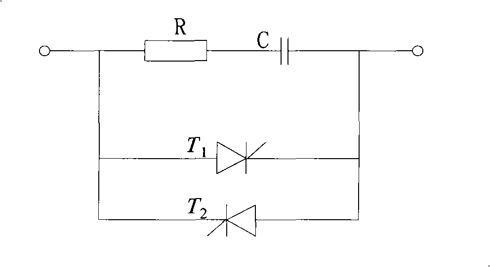
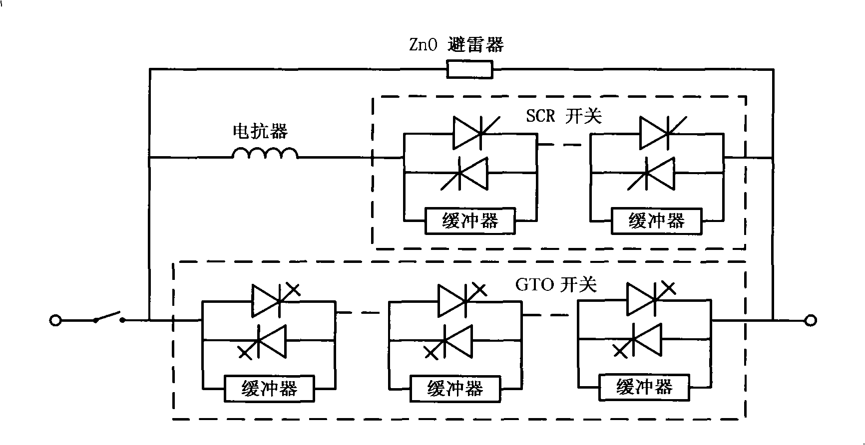
[0027] Such as figure 1 Shown is the circuit diagram of AC solid state circuit breaker, figure 2 An engineering example circuit diagram for the combination of a solid state circuit breaker and a current limiter.

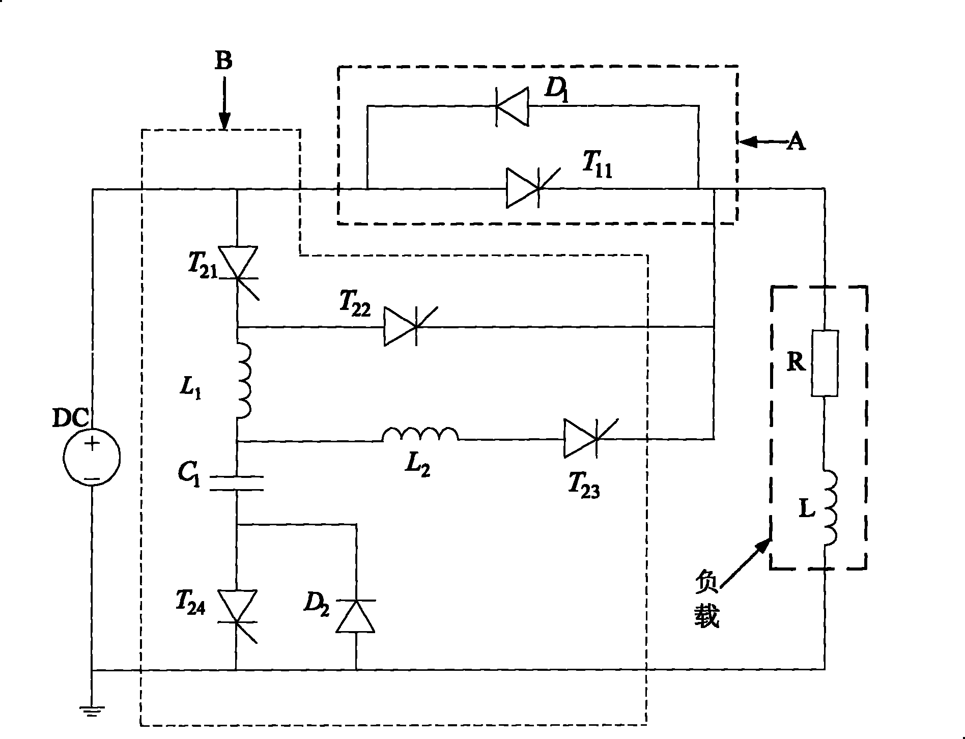
[0028] The circuit of the present invention such as image 3 Shown, where A is the main switch unit, B is the auxiliary switch unit. The main switch unit A includes: main switch thyristor T 11 and the main switching power diode D 1 ; The auxiliary switch unit B is mainly composed of the first thyristor T 21 , the second thyristor T 22 , the third thyristor T 23 , the fourth thyristor T 24 , inductance first inductance L 1 , the second inductance L 2 , energy storage pulse capacitor C 1 and auxiliary switching power diode D 2 composition.

[0029] Among them, the auxiliary switch circuit can be divided into:

[0030] (1) Auxiliary opening c...


PUM


Abstract

The invention discloses a resonance type DC solid circuit breaker which belongs to a solid circuit breaker and comprises a DC power supply, a main switching unit A, an auxiliary switching unit B and a load, wherein the main switching unit A comprises a main switching thyristor and a main switching power diode; the auxiliary switching unit B comprises a first thyristor, a second thyristor, a thirdthyristor, a fourth thyristor, a first inductor, a second inductor, an energy-storing impulse capacitor and an auxiliary switching power diode. The invention improves the capacity of the breaker, lowers the cost, realizes the soft starting (shutoff) of a solid switch, and improves the reliability of the breaker.

Description

technical field [0001] The invention relates to a solid state circuit breaker, in particular to a resonant DC solid state circuit breaker. Background technique [0002] Solid State Circuit Breaker (SSCB for short) is a new type of power automation equipment used to quickly cut off faults. At present, more AC solid state circuit breakers are used, and its structure is as follows: figure 1 As shown, it mainly consists of two parts: an RC snubber circuit and two solid-state switches connected in reverse parallel, wherein the solid-state switch can be a turn-off thyristor GTO (Gate Turn-Off Thyristor, referred to as GTO) or an insulated gate bipolar Type power tube IGBT (Insulated Gate Bipolar Transistor, referred to as IGBT). Due to the low overload capacity of existing commonly used power devices, solid-state circuit breakers are often used in combination with current limiters to achieve fault breaking under short-circuit conditions. Its structure is as follows: figure 2 A...

Claims


Application Information

Patent Timeline
Patent Type & Authority Patents(China)
IPC IPC(8): H02H3/087H03K17/73
Inventor 王莉胡杰
Owner NANJING UNIV OF AERONAUTICS & ASTRONAUTICS
Why Eureka
Try Eureka