Motor winding enamelled wire, iron core separation device and separation method

A technology of motor windings and separation devices, which is applied in the direction of electromechanical devices, electric components, and manufacturing motor generators, etc. It can solve the problems of no dust recovery, cumbersome operations, and large and complex devices, so as to adapt to a wide range of motors and separate processes. Safe and efficient separation operation

Inactive Publication Date: 2009-09-23
HEFEI UNIV OF TECH
View PDF2 Cites 20 Cited by
  • Summary
  • Abstract
  • Description
  • Claims
  • Application Information

AI Technical Summary

Problems solved by technology

This method is only suitable for individual maintenance or recycling. Although the equipment is simple, it is labor-intensive and low-efficiency. It is not suitable for mass production, and when the plastic is heated, it will produce toxic gas, which is harmful to health and is not conducive to environmental protection.
[0006] 3. Chinese patent CN2610553Y proposes a device for separating the iron core of the motor winding from the enameled wire. This device has poor adaptability to stator windings of different shapes and sizes, and the operation is cumbersome and unsafe.
The disadvantages are: the motor winding is required to rotate 360° with the fixture during the cutting process, which increases the complexity of the mechanism; the large amount of dust generated during cutting is not recycled; the winding iron core needs to be heated, which will produce toxic fumes; the enameled wire is It is pulled out by clusters, and the efficiency is low; cutting and pulling are not the same equipment, the whole device is huge and complicated, uses many motors, consumes a lot of energy, and is not easy to operate

Method used


Image

  • Motor winding enamelled wire, iron core separation device and separation method
  • Motor winding enamelled wire, iron core separation device and separation method

Examples


Embodiment Construction

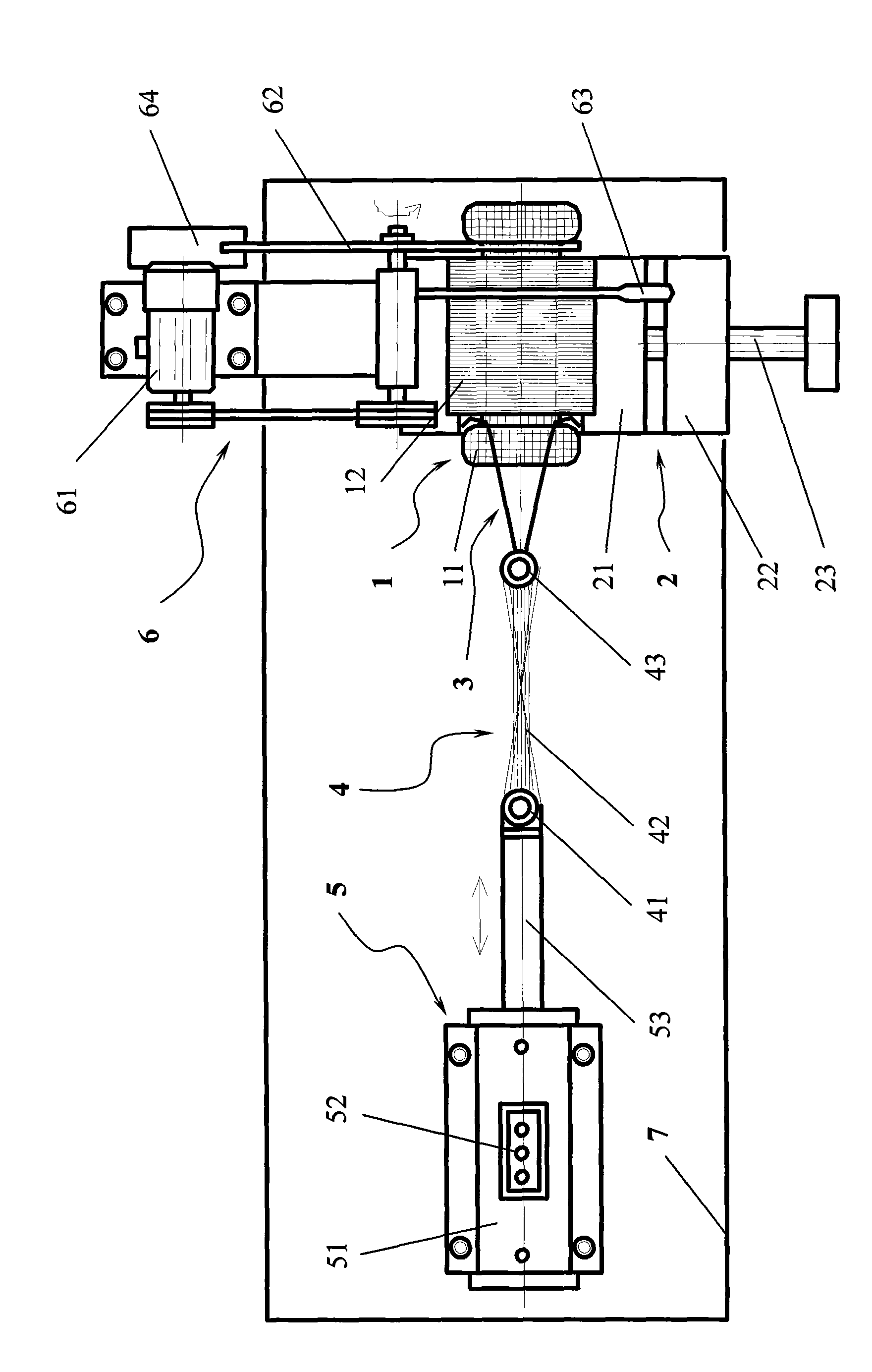
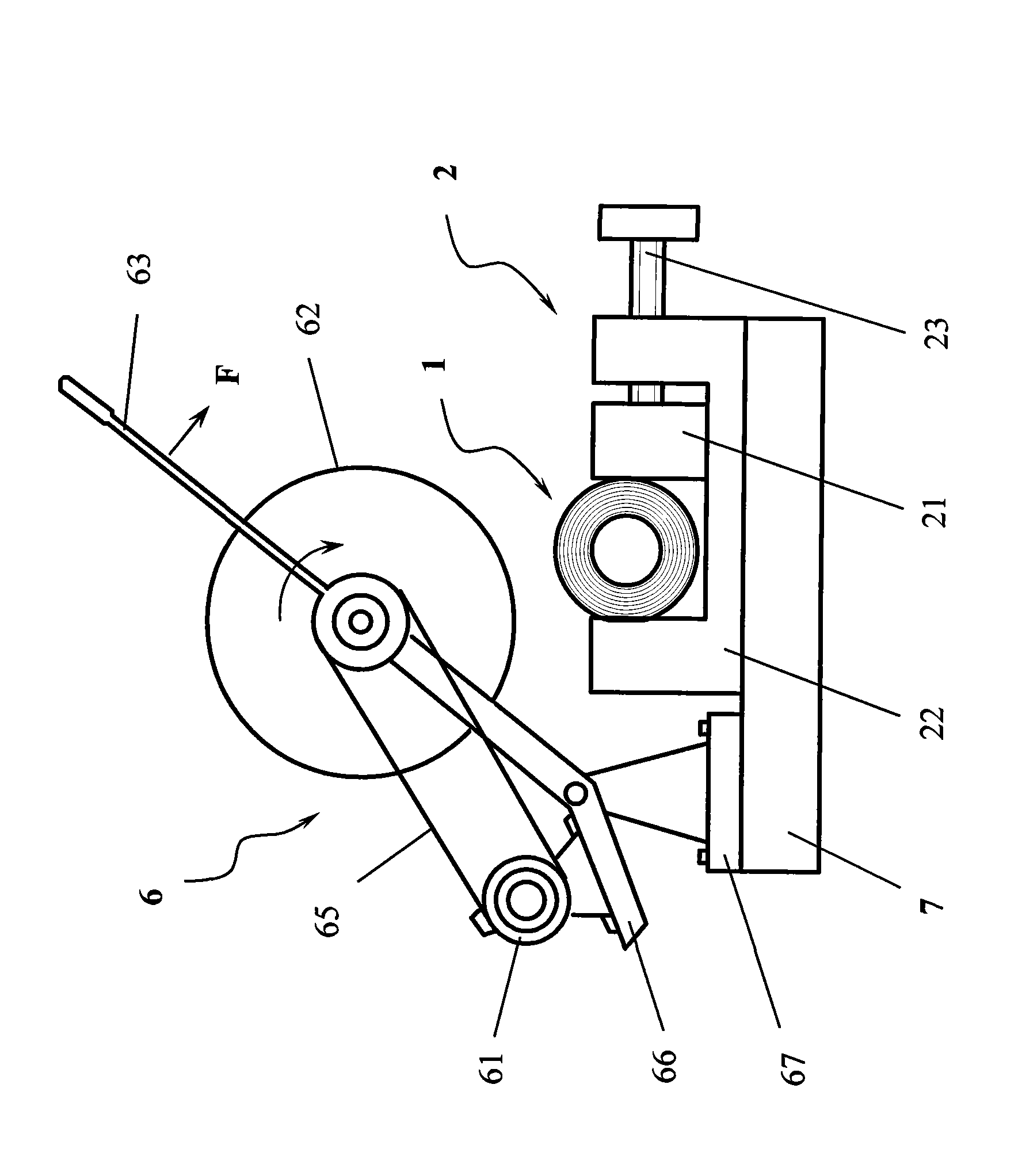
[0023] see figure 1 , a horizontal working platform 7 is set, on which the vise 2 for clamping the winding iron core 1 is fixed, and on one side of the vise 2, a cutting machine 6 is set, and the grinding wheel sheet 62 on the cutting machine 6 is in the winding enameled wire 11 On the right end position, the knife edge of the grinding wheel sheet 62 is parallel to the end face of the winding enameled wire 11; on the left side of the winding iron core 1, a cylinder 5 is arranged along the axial direction of the winding iron core 1, and the telescopic piston rod 53 in the cylinder 5 The front end of the bar is connected to the hook 3 that can be embedded in the left end of the winding enameled wire 11 through the steel wire rope 42 in the drag cable 4 .

[0024] figure 2 As shown, the flat-nose pliers 2 are composed of a pliers body 22 , a slider 21 and a screw rod 23 , and the rotation of the screw rod 23 pushes the slider 21 , so that the winding iron core 1 is clamped in t...


PUM


Abstract

A motor winding enamelled wire, an iron core separation device and a separation method are characterized in that a horizontal working platform is arranged; a pair of gripping tongs used for gripping the winding iron core are fixedly arranged on the working platform; a cutting machine is arranged at one side of the gripping tongs, a grinding wheel on the cutting machine is positioned at the right end of the winding enamelled wire and the edge of the grinding wheel is parallel to the end face of the winding enamelled wire; an air cylinder is arranged at the left side of the winding iron core along the axis direction of the winding iron core; and the front end of a flexible cylinder rod in the air cylinder is connected with a hook that can be embedded at the left end of the winding enamelled wire through an inhaul cable. The device is simple in structure, low in manufacturing cost, is applicable to a wide range of motors, and simple and convenient in operation. The method is safe and reliable in separation process, does not damage silicon-steel sheet, and is highly efficient, energy-saving and environment-friendly in separation operation.

Description

technical field [0001] The present invention relates to a tool, more particularly a device for separating enameled wires and iron cores of motor windings. Background technique [0002] Considering environmental protection and recycling of precious metals, it is very important to disassemble and recycle waste motors. However, there is still a lack of equipment for separating the enameled wire in the motor stator winding from the iron core. Most of them use manual separation, which is labor-intensive, low in efficiency, and prone to accidents. [0003] The separation methods in the prior art at home and abroad mainly include: [0004] 1. In European countries, the entire stator winding is cooled with liquid nitrogen first, and then crushed at low temperature. This method has high equipment costs, high energy consumption, high noise, and serious wear during the crushing process. The silicon steel sheets on the iron core cannot be reused after being crushed, and different meta...

Claims


Application Information

Patent Timeline
Patent Type & Authority Applications(China)
IPC IPC(8): H02K15/00
Inventor 王玉琳宋守许刘志峰刘光复朱家诚
Owner HEFEI UNIV OF TECH
Why Eureka
Try Eureka