Polymer electrolyte fuel cell and electrode/film/frame assembly manufacturing method

A polymer electrolyte and electrolyte membrane technology, applied in solid electrolyte fuel cells, fuel cell parts, fuel cells, etc., can solve problems such as damage to the electrolyte membrane 313, floating of the main part of the MEA, and insufficient maintenance of the MEA314, to achieve Improved jointability and reliable holding effect

Active Publication Date: 2009-09-23
PANASONIC CORP
View PDF4 Cites 5 Cited by
  • Summary
  • Abstract
  • Description
  • Claims
  • Application Information

AI Technical Summary

Problems solved by technology

[0013] In such a case, in the MEA-frame assembly 310, the MEA 314 may not be held sufficiently or the electrolyte membrane 313 may be damaged, and there is a problem that the cross leakage cannot be sufficiently reduced.
[0014] In addition, in the method of Patent Document 2, there is also a possibility that the main body of the MEA may float in the mold.

Method used


Image

  • Polymer electrolyte fuel cell and electrode/film/frame assembly manufacturing method
  • Polymer electrolyte fuel cell and electrode/film/frame assembly manufacturing method
  • Polymer electrolyte fuel cell and electrode/film/frame assembly manufacturing method

Examples


no. 1 approach

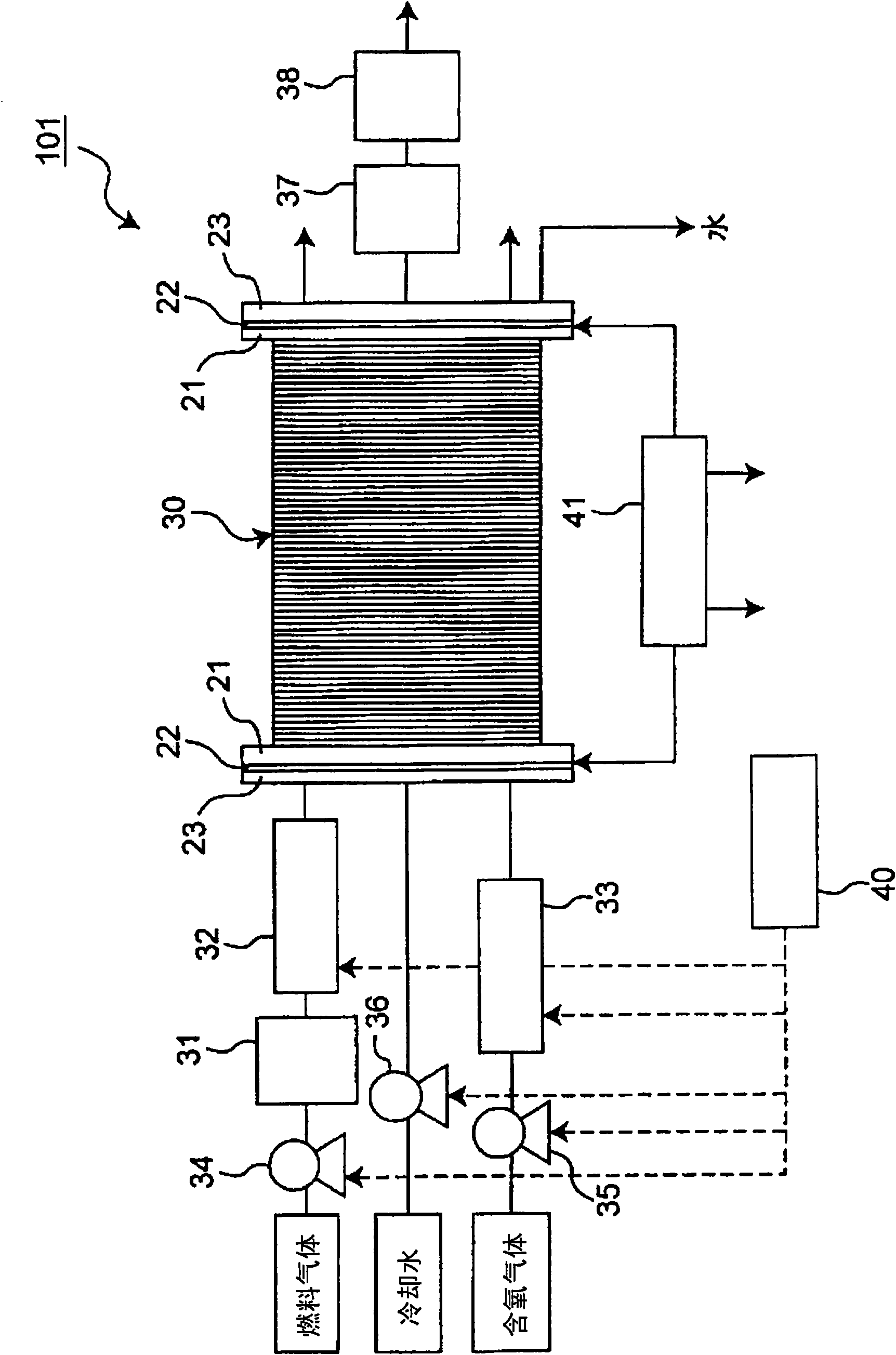
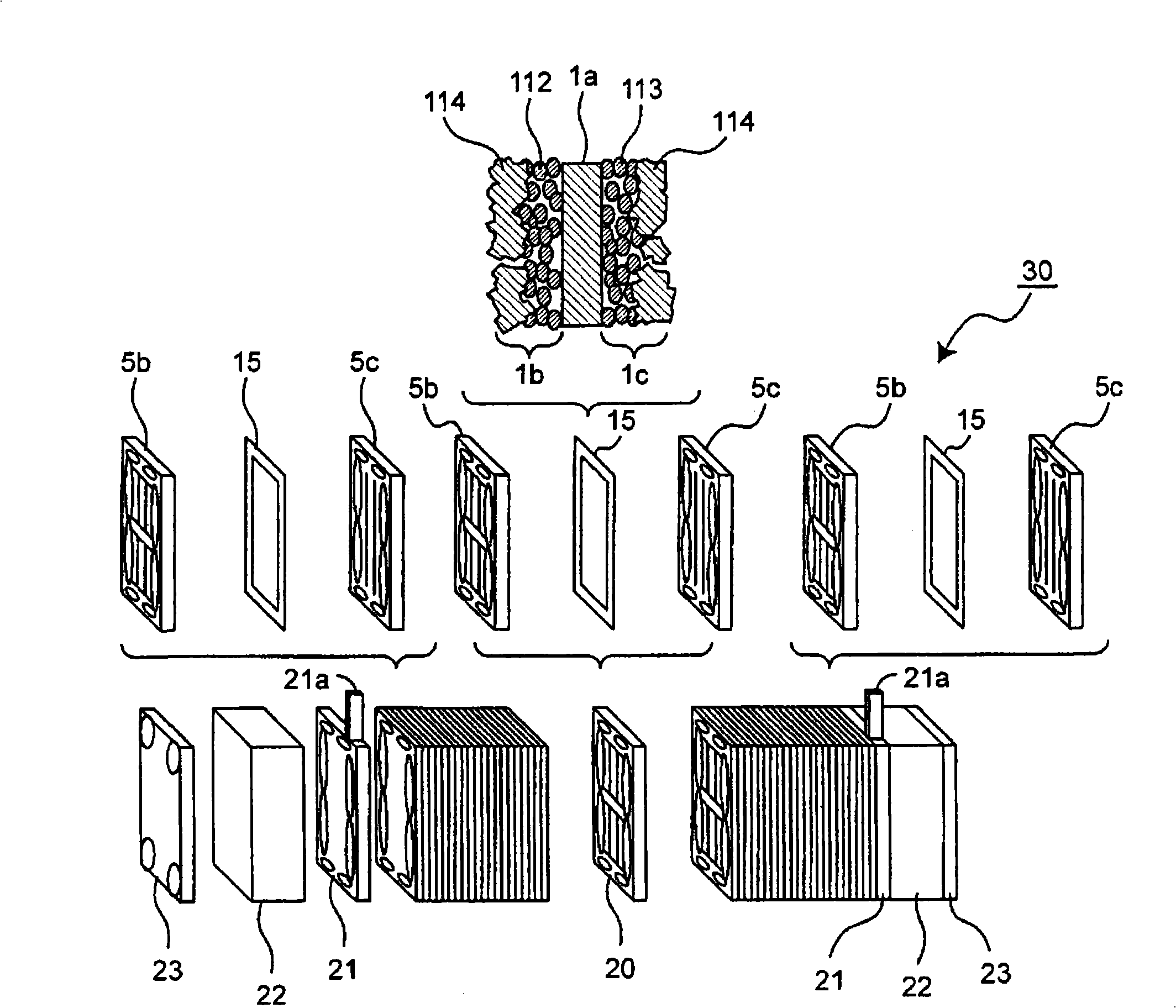
[0068] A schematic configuration diagram of a schematic configuration of a fuel cell including a fuel cell stack in the first embodiment of the present invention is shown in figure 1 . Additionally, the figure 1 A schematic exploded view of a fuel cell stack (hereinafter referred to as a fuel cell stack) included in the fuel cell 101 shown is shown in figure 2 .

[0069] The fuel cell 101 is, for example, a polymer electrolyte fuel cell (PEFC) that electrochemically reacts a hydrogen-containing fuel gas with an oxygen-containing oxidant gas such as air to simultaneously generate electricity, heat, and water. Such as figure 1 As shown, the fuel cell 101 includes: a stacked fuel cell stack 30 in which a plurality of fuel cell units (or single cells) having a pair of poles (or single cells) having an anode and a cathode are connected in series; a fuel processor for extracting hydrogen from fuel gas 31; an anode humidifier 32 for improving power generation efficiency by hu...

no. 2 approach

[0098] In addition, this invention is not limited to the said embodiment, It can implement in other various forms. For example, a schematic partial cross-sectional view of the MEA-frame assembly 85 included in the fuel cell in the second embodiment of the present invention is shown in Figure 10 . In addition, in the following description, the same reference number is used for the same structural member, and the description is abbreviate|omitted.

[0099] Such as Figure 10 As shown, the MEA-frame assembly 85 of the second embodiment has a structure in which a stepped portion 86 is formed in the first frame member 83, and the electrolyte membrane 1a is arranged on the lower stepped surface 86a of the stepped portion 86. The second frame member 84 is formed by injection molding so as to embed the stepped portion 86 in a state of being pressed and fixed by the pressing member 56 (through hole 84a ).

[0100] By adopting the structure of the second embodiment in this way, it i...


PUM


Abstract

Provided is a method for manufacturing an electrode / film / frame assembly of a fuel cell. In order to arrange a brim portion of an electrolyte film member on a first frame member, the first frame member and the electrolyte film member are placed in a first die for injection molding. Then, a second die is arranged to form a resin channel for forming the second frame member to be contact with the first frame member via the electrolyte film member. A fixing member provided in the second die presses a part of the brim portion of the electrolyte film member against the first frame member so as to be fixed. A molding resin material is introducedinto the resin channel to form the second frame member.

Description

technical field [0001] The present invention relates to a solid polymer electrolyte fuel cell, in particular to the improvement of the structure of the electrode-membrane-frame assembly of the fuel cell and its manufacturing method. Background technique [0002] Conventional solid polymer electrolyte fuel cells have used a unit cell assembly in which an MEA-frame assembly is sandwiched between an anode-side conductive separator and a cathode-side conductive separator. A membrane-electrode assembly (MEA) is held by a frame in which a gasket for sealing gas is disposed on a peripheral portion. The MEA is formed of a polymer electrolyte membrane, an anode joined to one side of the electrolyte membrane, and a cathode joined to the other side of the electrolyte membrane. Furthermore, gas supply parts for supplying fuel gas to the anode of the MEA and supplying oxidant gas to the cathode are formed on the peripheral edge of each separator. [0003] As a configuration of such a c...

Claims


Application Information

Patent Timeline
Patent Type & Authority Applications(China)
IPC IPC(8): H01M8/02H01M8/10
CPCH01M8/0273B29L2031/3468H01M2008/1095Y02E60/50B29C45/14467H01M8/0286Y02P70/50H01M4/86H01M8/02
Inventor 森本隆志日下部弘树松本敏宏川畑德彦吉村光生
Owner PANASONIC CORP
Why Eureka
Try Eureka