Process and device for reclaiming blown gas made from coal and by oxygen-enriched combustion

A technology of oxygen-enriched combustion and blowing air, which is applied in the combustion method, combustion type, indirect carbon dioxide emission reduction, etc. Effect

Inactive Publication Date: 2009-09-30
杭州东安科技有限公司
View PDF0 Cites 6 Cited by
  • Summary
  • Abstract
  • Description
  • Claims
  • Application Information

AI Technical Summary

Problems solved by technology

[0004] All the primary air and secondary air in this process use ordinary air. Since the content of oxygen in the air is 21%, and the content of nitrogen is 78%, only 21% of the oxygen in the air participates in the combustion of the fuel during combustion, while 78% % nitrogen will absorb a large amount of combustion heat and be discharged in the flue gas, causing environmental pollution and energy waste

Method used


Image

  • Process and device for reclaiming blown gas made from coal and by oxygen-enriched combustion
  • Process and device for reclaiming blown gas made from coal and by oxygen-enriched combustion

Examples


Embodiment 1

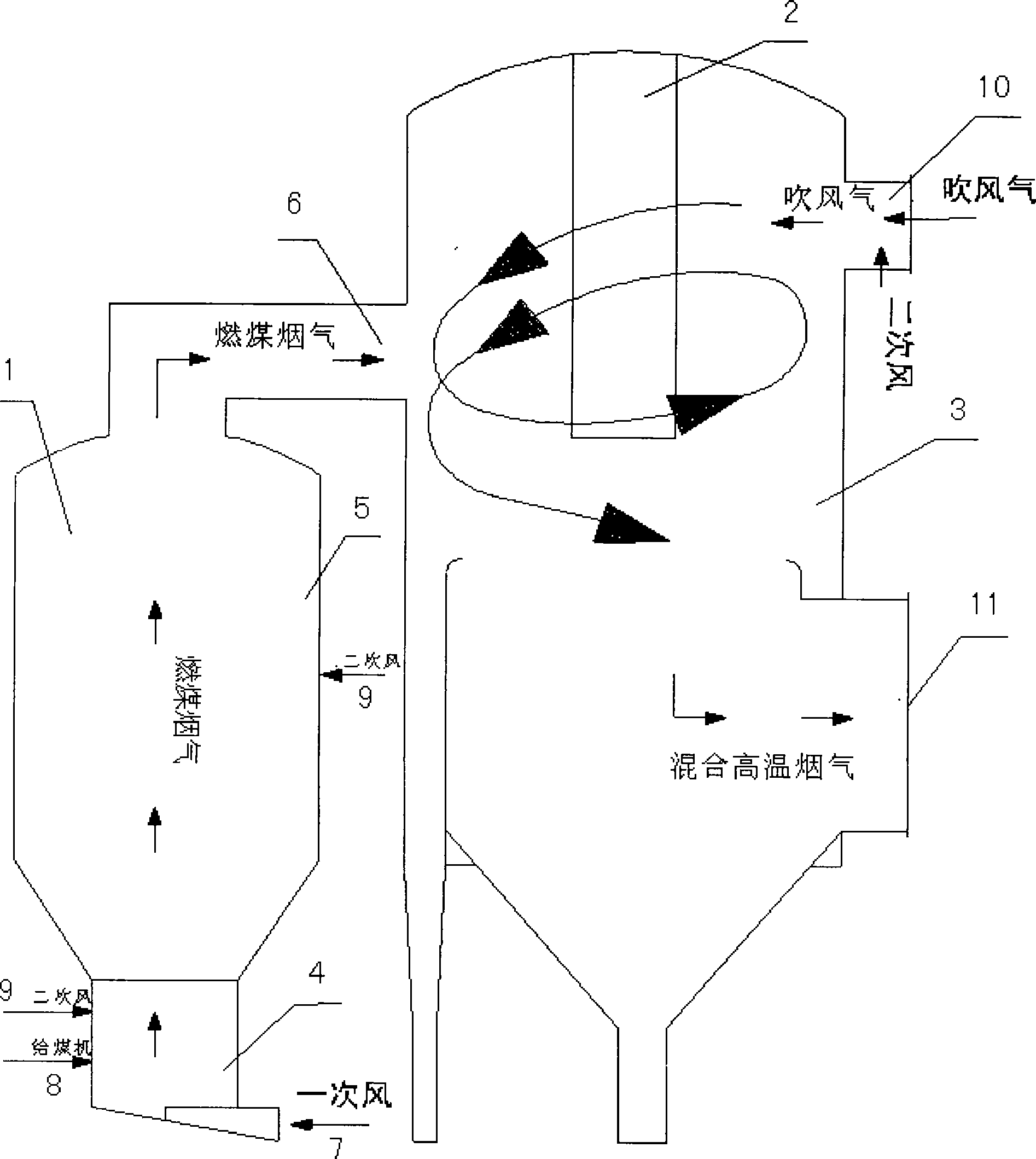
[0024] Embodiment 1: A preferred embodiment of the present invention is described as follows in conjunction with accompanying drawing: The technological process of the coal gas blowing gas recovery process of this oxygen-enriched combustion is as follows:

[0025] Gas-making coal slag and coal ash are sent to the bottom of the fluidized furnace by the screw feeder, and are fluidized by the primary air (ordinary air or oxygen-enriched air) with a temperature of 120°C±12°C after heat exchange by the air preheater. Continue to burn in the secondary air (oxygen-enriched air), and produce high-temperature flue gas at 950~1000°C, which enters the cyclone dust collector in the blowing gas combustion furnace, and the flue gas is removed by the cyclone dust collector After dust, it enters the blowing gas combustion furnace from the top of the cyclone dust collector. Under the action of the secondary air (oxygen-enriched air), the blowing gas is completely combusted, and the temperature ...

Embodiment 2

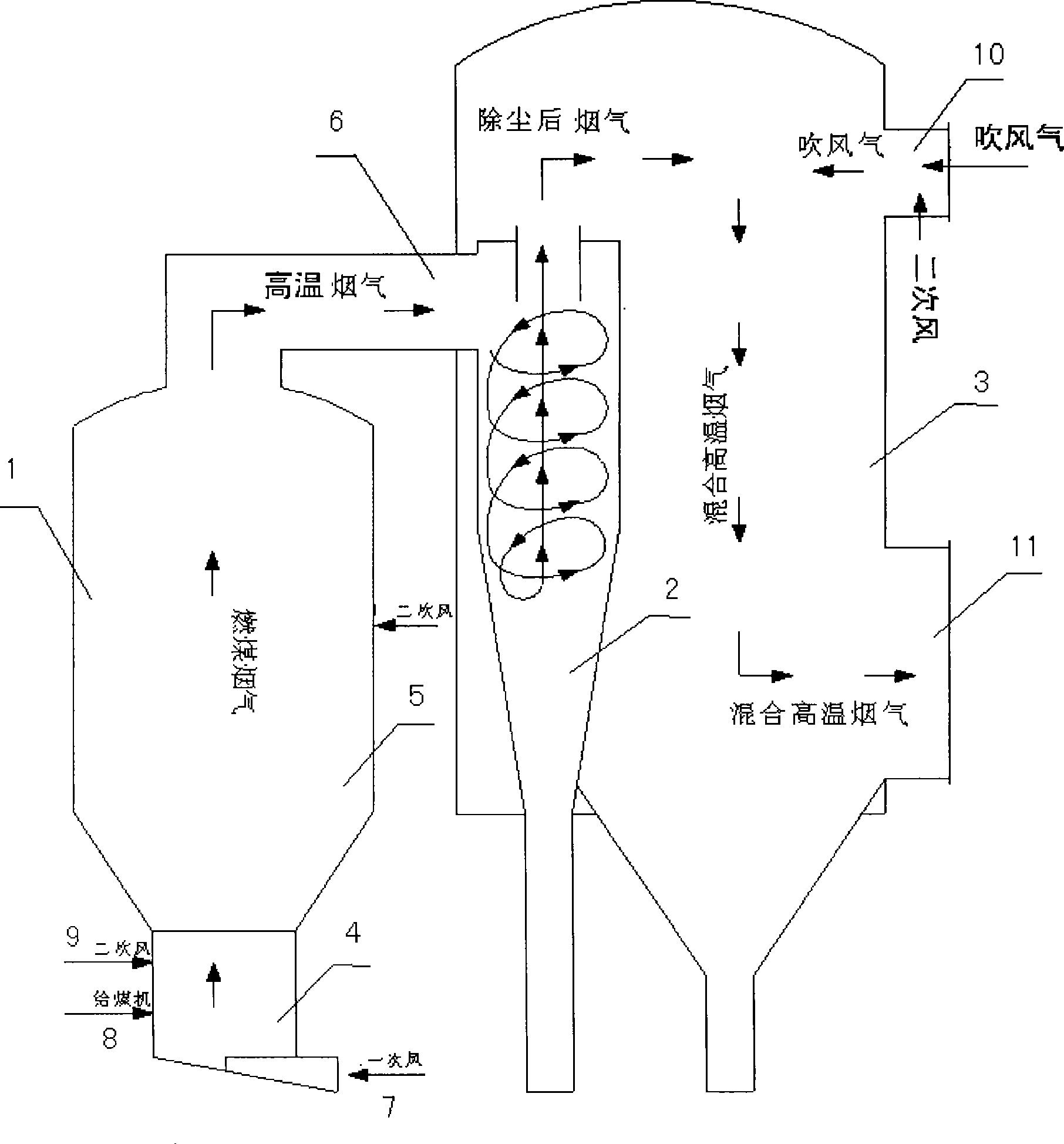
[0027] Embodiment two: see figure 1 , this coal gas blowing gas recovery device is basically the same as the device in Embodiment 1, see figure 2 , the difference is: cyclone dust collector 2 is replaced by a cyclone.


PUM


Abstract

The invention relates to a process and a device for reclaiming blown gas made from coal and by oxygen-enriched combustion. The flow of the reclaiming process comprises that: gas making furnace residue and coal ash are sent to the lower part of a fluidized bed furnace through a screw-type coal feeder and subjected to heat exchange through an air preheater, primary air fluidization at the temperature of approximately 120 DEG C and partial combustion reaction; uncombusted portions are continuously combusted in secondary air and generate high-temperature flue gas at the temperature of between 950 and 1,000 DEG C which enters a cyclone dust collector in a blown gas combustion furnace; flue gas subjected to dust collection by the cyclone dust collector is drained into the blown gas combustion furnace from the top of the cyclone dust collector; the blown gas is completely combusted under the action of the secondary air; flue gas reaches the temperature of between 950 and 1,050 DEG C, is drained out from the blown gas combustion furnace and enters a boiler system; and finally flue gas at the temperature of between 130 and 150 DEG C is emptied by chimneys. The device of the reclaiming process comprises the fluidized bed furnace, the blown gas combustion furnace and the cyclone dust collector, wherein a furnace chamber of the fluidized bed furnace is communicated with the cyclone dust collector in the blown gas combustion furnace through a flue; the lower part of the fluidized bed furnace is provided with a primary air and fuel inlet, and the lower part and the middle part of the fluidized bed furnace are provided with a secondary air inlet respectively; the inside of the blown air combustion furnace is provided with the cyclone dust collector; and the upper part of the blown air combustion furnace is provided with a blown gas inlet and the lower part of the blown air combustion furnace is provided with a flue gas outlet pipe.

Description

technical field [0001] The invention relates to a process and device for comprehensive recycling of waste gas, waste residue and waste ash produced in the process of coal gas production, in particular to a process and device for recovering blown air from coal gas produced by oxygen-enriched combustion. Background technique [0002] At present, the technological process of coal gas blowing gas recovery is to combine the fluidized fluidized furnace with the waste heat recovery of the blowing gas. When the system is running, the fluidized fluidized furnace is first ignited. The blowing air is sent to the blowing gas combustion furnace, and the high-temperature flue gas of the fluidized fluidized furnace is used to ignite the gas-making blowing gas, and the high-temperature flue gas produced by slag and fly ash is used to ignite the gas-making blowing gas. [0003] Process introduction: The gas-making slag and coal ash are sent to the lower part of the fluidized fluidized furnac...

Claims


Application Information

Patent Timeline
Patent Type & Authority Applications(China)
IPC IPC(8): F23G7/06
CPCY02E20/34
Inventor 胡鸿频
Owner 杭州东安科技有限公司
Why Eureka
Try Eureka