A workpiece provided with aluminum and chromium hard material layer and a preparation method thereof
A workpiece and condition technology, applied in the field of parts, can solve problems such as chromium/aluminum distribution fluctuations
- Summary
- Abstract
- Description
- Claims
- Application Information
AI Technical Summary
Problems solved by technology
Method used
Image
Examples
Embodiment 1
[0052] Example 1: Milling of structural steel
[0053] Tools: end mill, hard metal
[0054] Diameter D=8mm, number of teeth z=3
[0055] Material: Structural steel Ck45, DIN 1.1191
[0056] Milling parameters:
[0057] cutting speed v c =200 / 400m / min
[0058] Feed speed v f =2388 / 4776mm / min
[0059] Radial engagement width a e =0.5mm
[0060] Axial engagement width a p =10mm
[0061] Cooling: Emulsion 5%
[0062] Process: down milling
[0063] Wear criteria: cutting surface wear VB = 0.12mm
[0064]
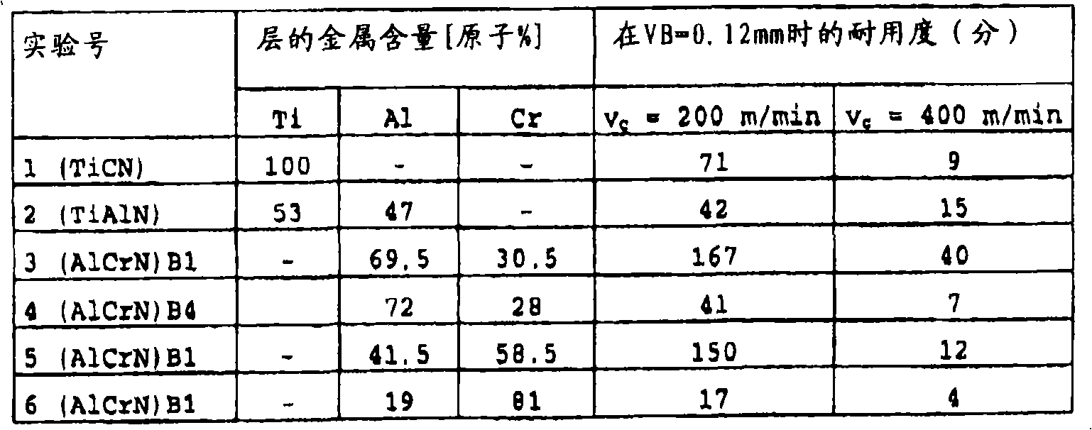
[0065] Example 1 shows a comparison of the service life of coated HM milling cutters tested at different cutting parameters.
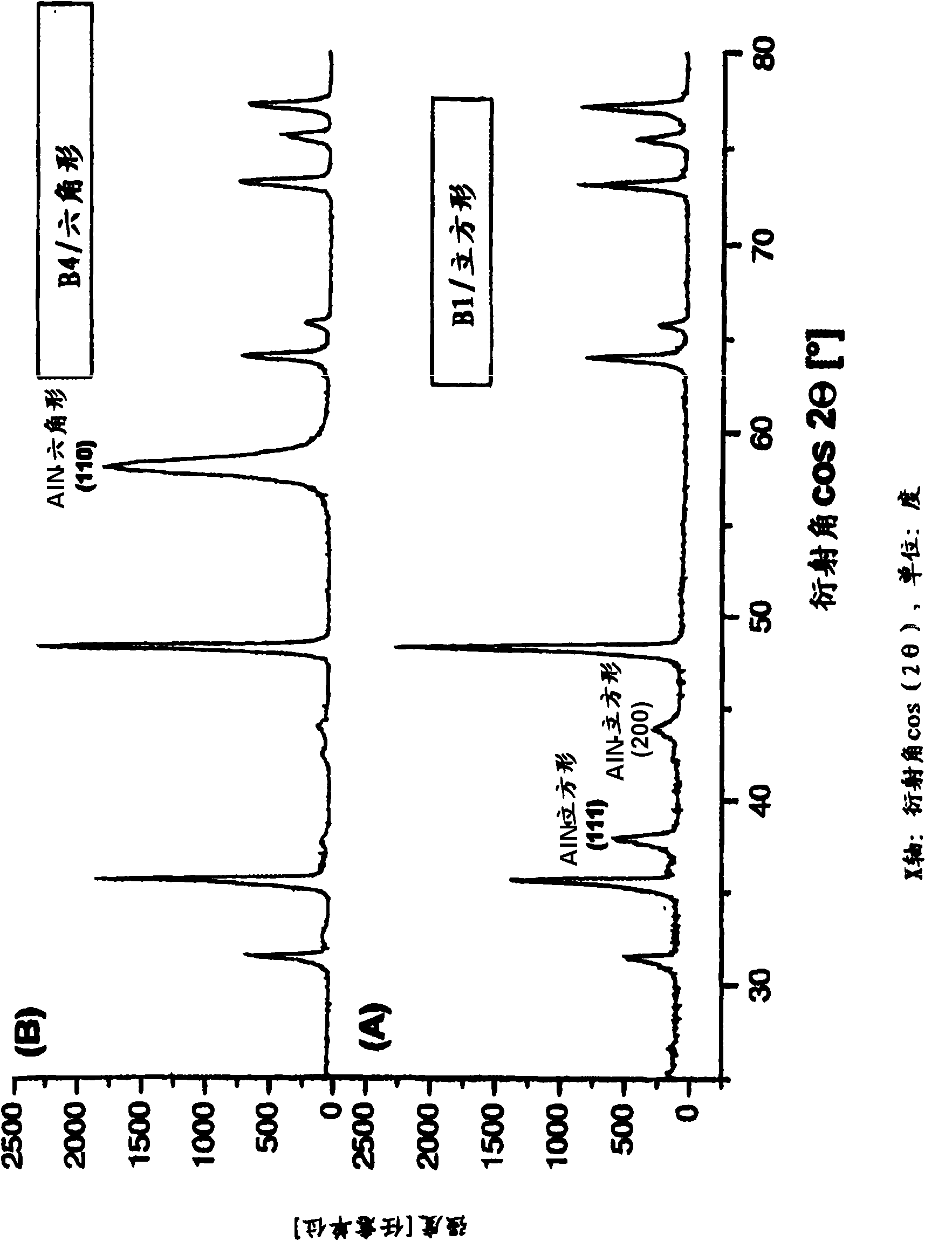
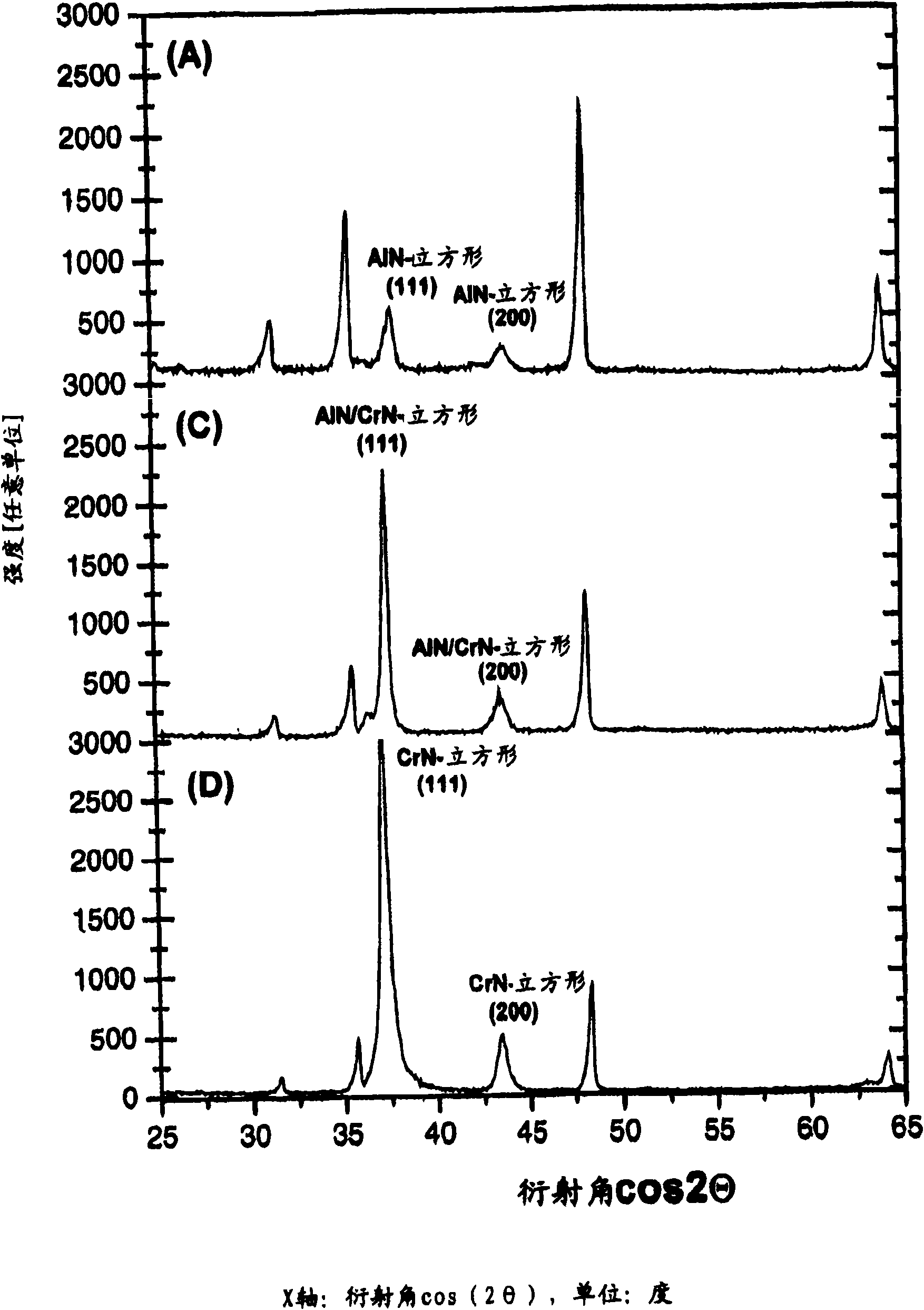
[0066] It is evident that the described AlCrN layer has a longer service life than the layer systems used hitherto industrially, such as TiCN and TiAlN. Furthermore, it can be seen from the results that, as in the case of Example 1 with a high Al content, only the cubic B1 structure is maintained. Then, the durability characteristic was ...
Embodiment 2
[0067] Example 2: Milling of austenitic steel
[0068] Tools: end mill, hard metal
[0069] Diameter D=8mm, number of teeth z=3
[0070] Material: Austenitic steel X6CrNiMoTi 17 12 2, DIN 1.4571
[0071] Milling parameters:
[0072] cutting speed v c =240m / min
[0073] Tooth feed f z =0.08mm
[0074] Radial engagement width a e =0.5mm
[0075] Axial engagement width a p =10mm
[0076] Cooling: Emulsion 5%
[0077] Process: down milling
[0078] Wear criteria: cutting surface wear VB = 0.1mm
[0079]
[0080] Example 2 shows a comparison of the service life of coated HM milling cutters. The AlCrN layer achieves improved wear properties compared to industrially used hard layers. The increase in service life in the case of AlCrN is due on the one hand to the as yet unproven lower propensity for material lubrication of the second alloying element Cr compared to Ti in the TiAlN layer and on the other hand to the The excellent wear resistance and high hardness of t...
Embodiment 3
[0081] Example 3: Milling of hardened steel
[0082] Tool: Spherical milling cutter, hard metal
[0083] Diameter D=10mm, number of teeth z=2
[0084] Material: K340 (62HRC), corresponding to C 1.1%, Si 0.9%, Mn 0.4%, Cr 8.3%, Mo 2.1%, V 0.5%
[0085] Milling parameters:
[0086] cutting speed v c =0-120m / min
[0087] Tooth feed f z =0.1mm
[0088] Radial engagement width a e =0.2mm
[0089] Axial engagement width a p =0.2mm
[0090] Cooling: dry
[0091] Process: Climb and up milling, finishing
[0092] Wear criteria: cutting surface wear VB = 0.3mm
[0093]
PUM
| Property | Measurement | Unit |
|---|---|---|
| Drilling depth | aaaaa | aaaaa |
| Diameter | aaaaa | aaaaa |
Abstract
Description
Claims
Application Information
 - R&D
- Intellectual Property
- Life Sciences
- Materials
- Tech Scout
- Unparalleled Data Quality
- Higher Quality Content
- 60% Fewer Hallucinations
Browse by: Latest US Patents, China's latest patents, Technical Efficacy Thesaurus, Application Domain, Technology Topic, Popular Technical Reports.
© 2025 PatSnap. All rights reserved.Legal|Privacy policy|Modern Slavery Act Transparency Statement|Sitemap|About US| Contact US: help@patsnap.com


