Driving device for electric toothbrush

A driving device and electric toothbrush technology, applied in electromechanical devices, electric components, dentistry, etc., can solve the problems of reduced efficiency, large magnetic field energy loss, complex process, etc., achieve smooth reciprocating motion, reduce magnetic field loss, and simple winding process Effect

Active Publication Date: 2009-10-14
DONGGUAN LEBOND ELECTRONICS TECH CO LTD
View PDF1 Cites 27 Cited by
  • Summary
  • Abstract
  • Description
  • Claims
  • Application Information

AI Technical Summary

Problems solved by technology

[0003] In a traditional electric toothbrush, this conversion mechanism is usually a gear mechanism or a cam mechanism to convert the continuous rotational motion of the drive shaft of the motor into a reciprocating linear motion of the drive shaft of the motion conversion mechanism or reciprocate around the central axis of the drive shaft Rotational movement, due to the existence of the conversion mechanism, it is difficult to move the toothbrush head at high speed, thus limiting the effect of removing plaque.
[0004] And in the prior art, as Chinese patent " electric toothbrush ", application number is: 200380100676.8, this electric toothbrush comprises toothbrush head and is used to move the actuator of this toothbrush head, and this actuator is the driving device of this electric toothbrush, It includes a drive shaft, a first magnetic circuit for reciprocating the drive shaft up and down, and a second magnetic circuit for reciprocating rotation of the drive shaft; and the second magnetic circuit is mainly generated by an inverter in the circuit Periodically changing voltage to drive the coil to generate periodically changing current. From the structure of the patent, the coil is a solenoid structure, and the current in the coil generates a changing magnetic field, thereby magnetizing the shoe-shaped pole yoke passing through the solenoid, thereby making the The solenoid shoe-shaped pole yoke produces alternating magnetic poles, which interact with the rotor to cause the drive shaft to generate reciprocating rotation; since the coil current is magnetized by the solenoid through the solenoid shoe-shaped pole yoke, due to the two shoe-shaped poles The yoke is set separately. First, the assembly process is complicated. Second, the structure of the magnetic circuit becomes complicated, and the magnetic resistance is very large, which leads to a large loss of magnetic field energy and a decrease in efficiency.

Method used


Image

  • Driving device for electric toothbrush
  • Driving device for electric toothbrush
  • Driving device for electric toothbrush

Examples


Embodiment Construction

[0035] Below in conjunction with accompanying drawing, specific embodiment is described:

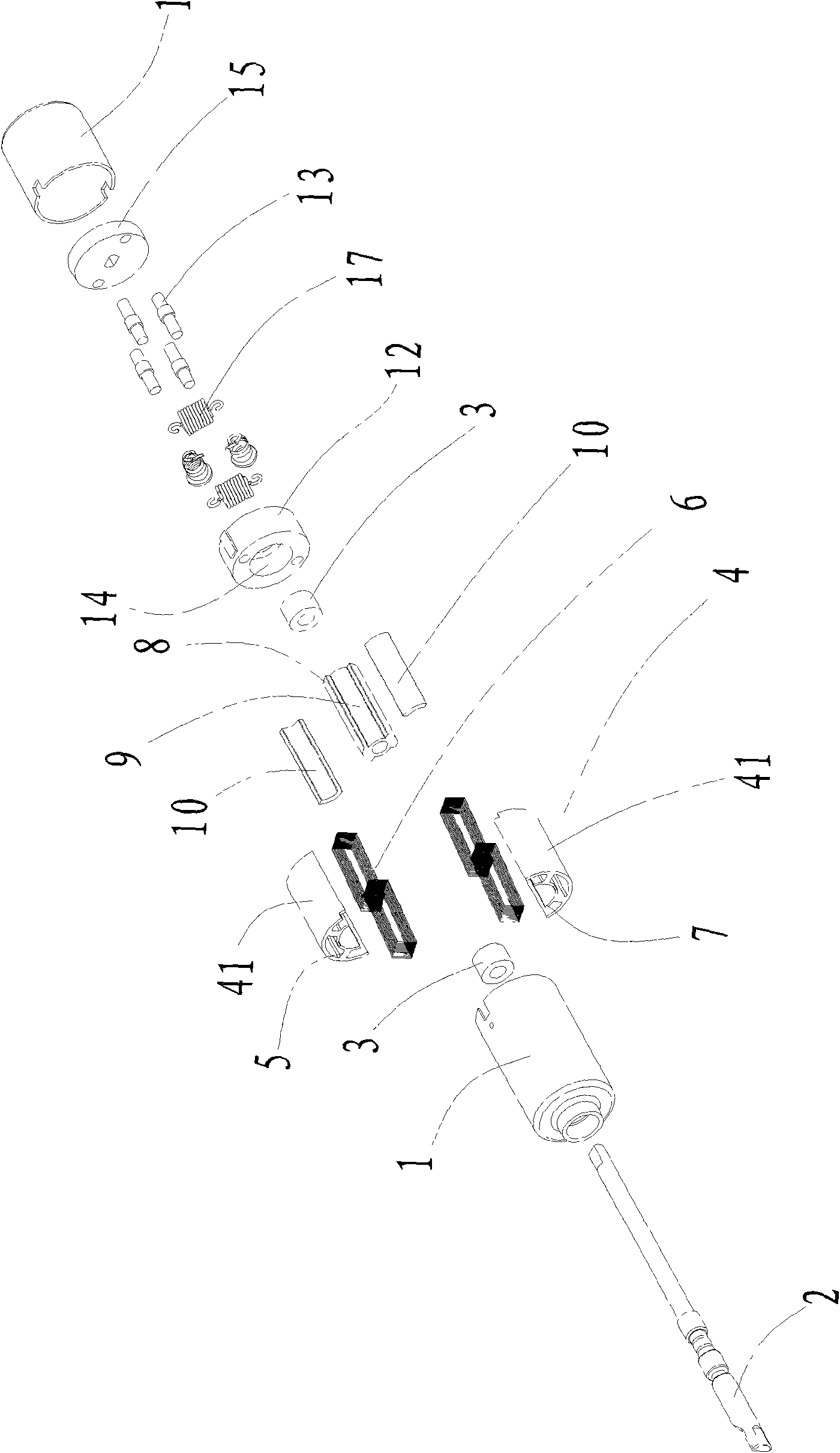
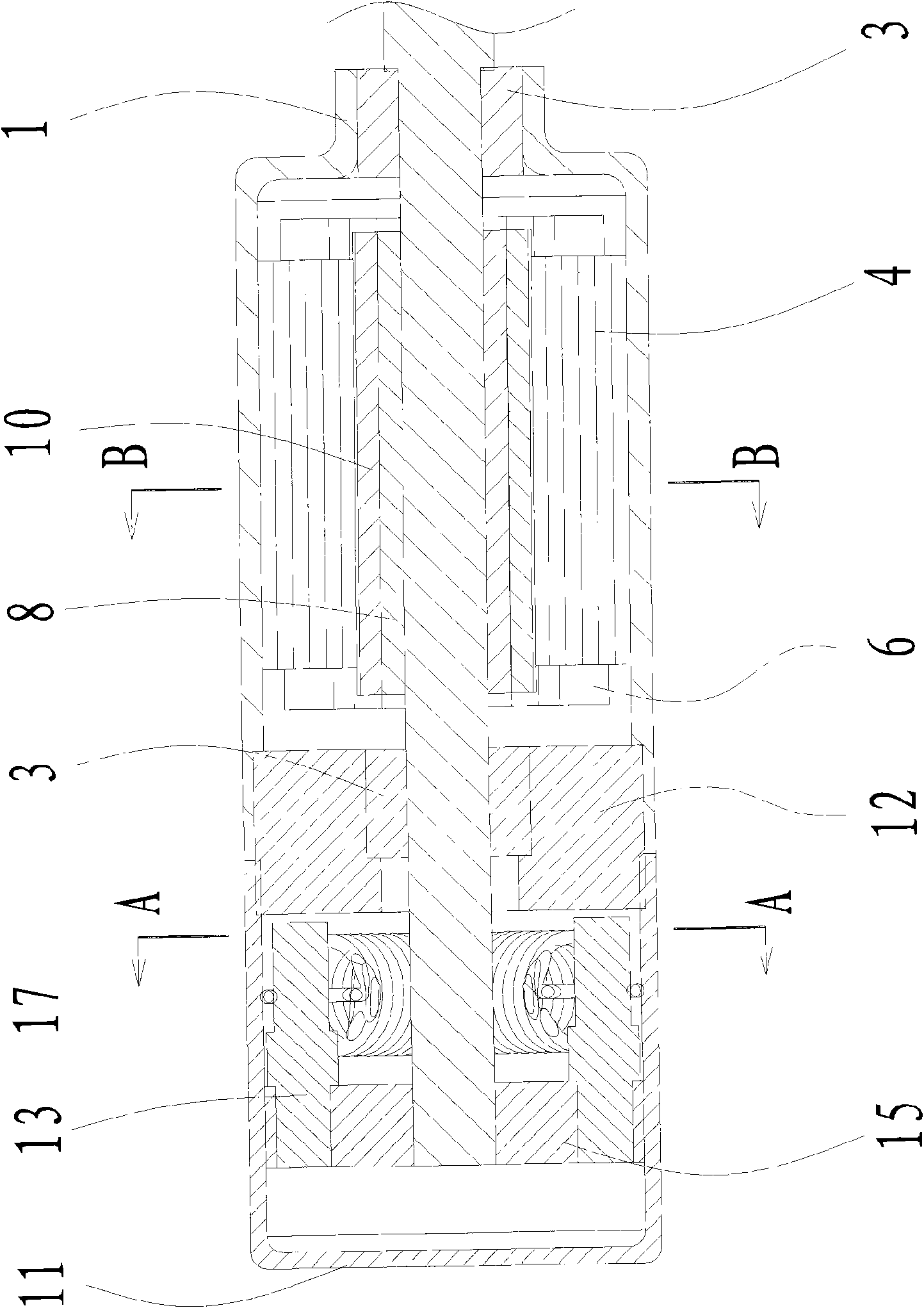
[0036] Specific embodiment one of the present invention, such as figure 2 , image 3 , shown in Fig. 4 and Fig. 5, a kind of electric toothbrush drive device, comprises a drive circuit and the housing 1 of sealing dust-proof and supporting function together, also comprises a drive rotating shaft 2, and the two ends necks of rotating shaft 2 are respectively equipped with a Bearing 3, the bearing 3 is fixedly installed in the inner cavity of the housing 1; a coil fixing frame 4 is sleeved in the inner cavity of the housing 1, and the inner surface of the coil fixing frame 4 evenly protrudes inwards to have four shoe-shaped pole yokes 5. Each shoe-shaped pole yoke 5 is wound with a drive coil 6, and the drive coil 6 is connected to the electrodes of the drive circuit. The end of each shoe-shaped pole yoke 5 is also connected to an arc-shaped pole yoke 7, four arcs The pole yoke 7 forms ...


PUM


Abstract

The invention discloses a driving device for an electric toothbrush, which comprises a driving circuit, an external shell, a revolving shaft, a bearing, a coil fixing bracket, a boot shape pole yolk, a driving coil, a magnet positioning post, a permanent magnet, an end cover and a damping device which is used for assisting the revolving shaft to do reciprocating movement; a common rotor and a common stator are adopted to control the current direction of the coil in the rotor in a matching manner so as to change the direction of the magnetic field and cause the rotor to rotate with high frequency in a reciprocating way; the alternating magnetic field in the stator is generated by adopting alternating rectangular wave current; the setting of the driving circuit is simpler and is beneficial to control; the coil fixing bracket is formed by the abutment joint of two semi-circular iron cores, which causes the winding process of the coil to become simpler; in addition, the fixing bracket is formed by overlying of multiple lays of magnetic conducting elements, which ensures that the magneto resistance and the eddy current of a middle magnetic loop are relatively decreased, reduces the lossof the magnetic field, improves the efficiency and has simple structure; the revolving shaft is also provided with the damping device for assisting the movement of the alternating magnetic field, thus causing the reciprocating movement of the revolving shaft to be smoother and greatly improving the system efficiency.

Description

technical field [0001] The invention relates to personal cleaning products, in particular to an electric toothbrush driving device. Background technique [0002] In a traditional electric toothbrush, the rotational motion of the drive shaft of the motor is converted into a reciprocating linear motion or a reciprocating rotational motion by a motion conversion mechanism. The drive shaft installed in the motion conversion mechanism is the toothbrush head reciprocating or Rotate reciprocally around the central axis of the drive shaft. [0003] In a traditional electric toothbrush, this conversion mechanism is usually a gear mechanism or a cam mechanism to convert the continuous rotational motion of the drive shaft of the motor into a reciprocating linear motion of the drive shaft of the motion conversion mechanism or reciprocate around the central axis of the drive shaft Rotational movement, due to the existence of the conversion mechanism, it is difficult to move the toothbru...

Claims


Application Information

Patent Timeline
Patent Type & Authority Applications(China)
IPC IPC(8): A61C17/34
CPCA61C17/3445H02K1/278H02K1/146A61C17/3472A61C17/3418H02K33/16H02K5/1672
Inventor 黄拔梓
Owner DONGGUAN LEBOND ELECTRONICS TECH CO LTD
Why Eureka
Try Eureka