
Fuel cell engine system and starting method thereof

An engine system and fuel cell technology, applied in the direction of fuel cells, fuel cell additives, fuel cell grouping, etc., can solve problems such as complex control systems, troublesome startup, and poor reliability of lithium batteries, and achieve simple system structure and convenient startup and operation , the effect of wide applicability

Active Publication Date: 2011-05-18
SUNRISE POWER CO LTD
View PDF2 Cites 0 Cited by
  • Summary
  • Abstract
  • Description
  • Claims
  • Application Information

AI Technical Summary

Problems solved by technology

[0004] It is easier to start the electric-electric hybrid fuel cell engine because of the ready-made power, but it is more troublesome for the pure fuel cell engine
There are usually the following starting methods: one is to use low-voltage control power to start with DC / DC boost. The disadvantage of this method is that it requires a large control power supply capacity, which is generally difficult to meet the requirements.
The second is to use the method of increasing the high-voltage starting power supply. Generally, lead-acid batteries are used as high-voltage power supplies. The disadvantage of this method is that the output voltage of lead-acid batteries is usually 12V, and it is necessary to use multiple lead-acid batteries in series to meet the needs. This will inevitably increase the weight and space of the engine, which is difficult for the engine to do; the third is to use a lithium battery for electric and electric hybrid use. The disadvantages of this method are: the reliability of lithium batteries is poor, and the cost is high , the control system is also more complicated, and the lithium battery meets the voltage and capacity requirements, and a lot of installation is required, and the weight and volume are also large

Method used


Image

  • Fuel cell engine system and starting method thereof
  • Fuel cell engine system and starting method thereof
  • Fuel cell engine system and starting method thereof

Examples


Embodiment Construction

[0024] The present invention will be further described below in conjunction with the embodiment that accompanying drawing provides.

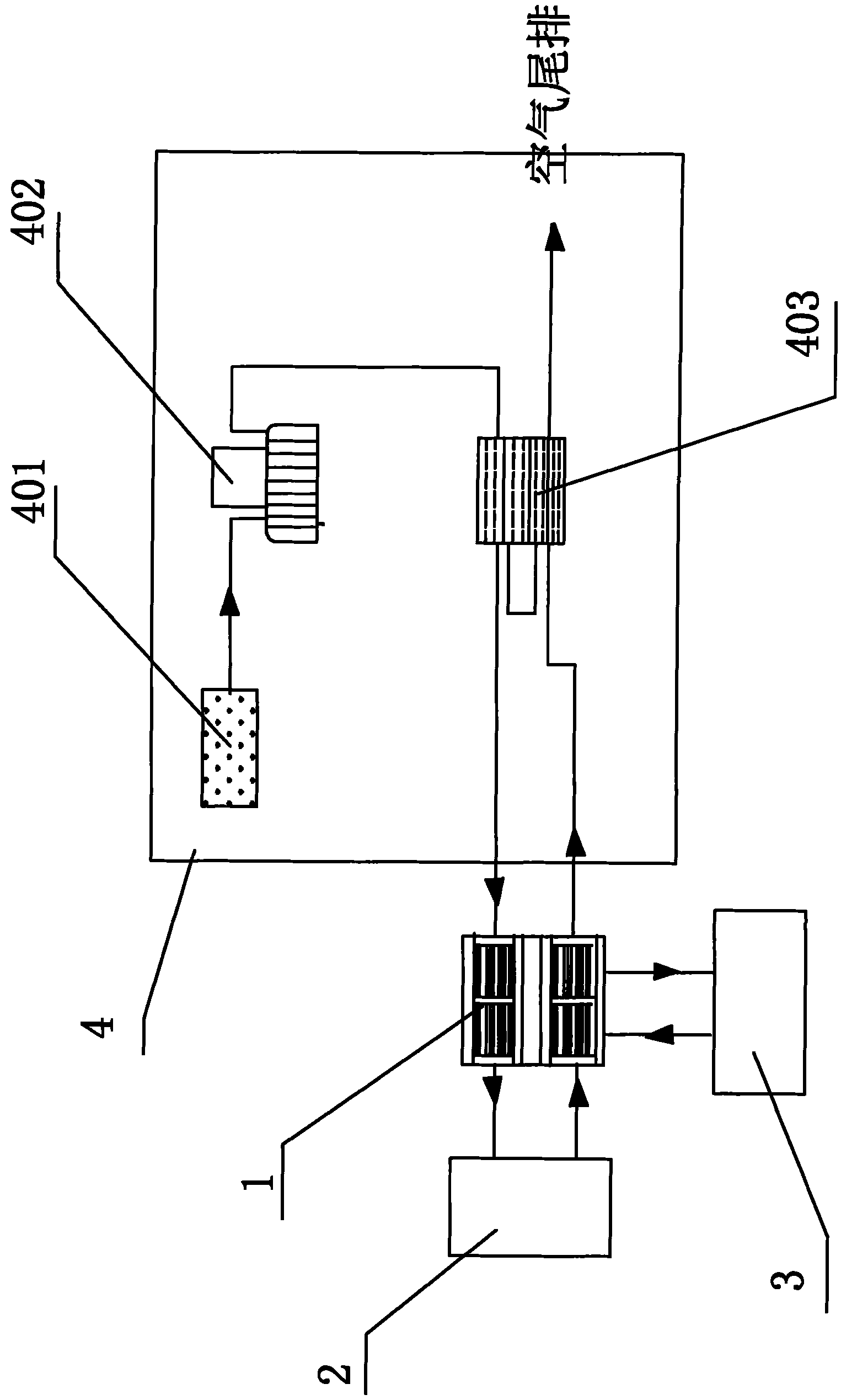
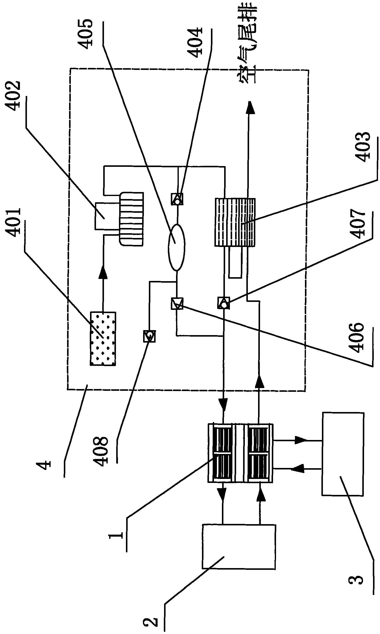
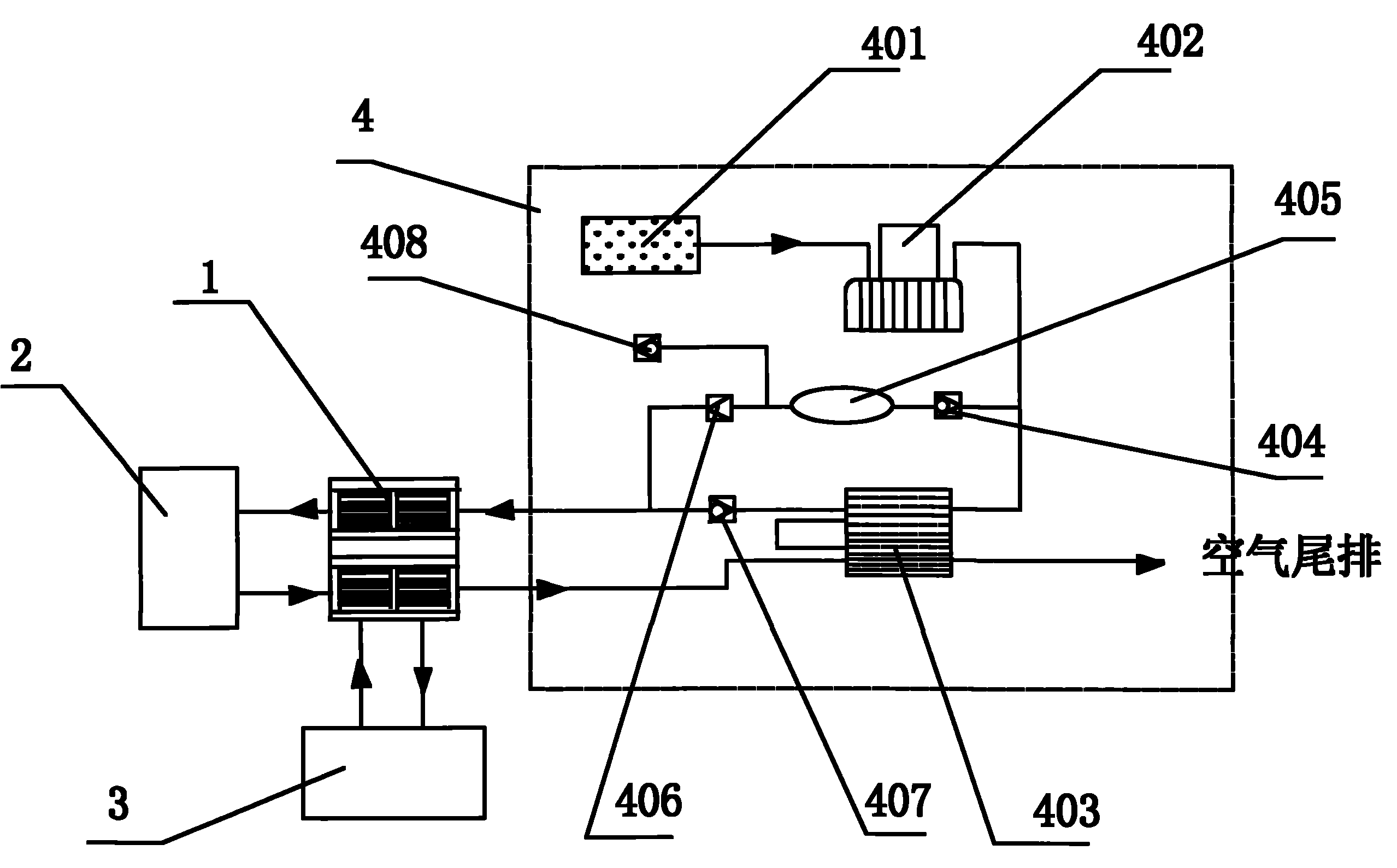
[0025] The embodiment is a 10kW fuel cell engine system with a maximum air operating pressure of 0.05MPa, including a fuel cell stack 1 , a hydrogen system 2 , an air system 4 and a cooling system 3 . The air system includes an air filter 401, an air supply device 402 and a wet enthalpy conversion device 403 connected by pipelines, and an outlet is connected in series on the pipeline between the air outlet of the wet enthalpy conversion device 403 and the air inlet of the fuel cell stack 1 One-way valve 407, the air outlet of the outlet one-way valve 407 is connected with the air inlet of the fuel cell stack 1, the air inlet of the outlet one-way valve 407 is connected with the air outlet of the wet enthalpy conversion device 403; the air system also includes an additional branch The additional branch is composed of an additional branch check va...


PUM


Abstract

The invention relates to a fuel cell engine system and a starting method thereof; wherein the fuel cell engine system comprises a fuel cell stack, a hydrogen system, an air system and a cooling system; the air system comprises an additional branch circuit comprising an additional branch circuit retaining valve, a gas storage device, a magnetic valve and a fast-assembly gas precharge valve; the starting method of the fuel cell engine system is as follows: the fuel cell engine system is started; the hydrogen system supplies the hydrogen to the fuel cell stack; the compressed air stored in the gas storage device of the additional branch circuit is supplied to the fuel cell stack; after the fuel cell stack generates electricity, the fuel cell stack supplies power to the air feeder of the air system for realizing that the air feeder supplies air to the fuel cell stack while charging the gas storage device on the additional branch circuit. The invention has the advantages that the high voltage source does not need to be added; the cost is reduced; the system has simple structure, is convenient to manufacture, and occupies little space; the system start-up operation is convenient, safe and reliable; and the system has extensive applicability.

Description

technical field [0001] The invention belongs to the field of fuel cells, in particular to a proton exchange membrane fuel cell engine starting. Background technique [0002] Proton exchange membrane fuel cell can be used as a power plant for cars and boats. The working mode of an engine powered by a proton exchange membrane fuel cell is similar to that of an internal combustion engine. It must continuously feed hydrogen fuel and oxidant into the battery, and continuously discharge reaction product water and certain waste heat to maintain the balance of battery materials and heat. Therefore, in order to maintain the continuous operation of the proton exchange membrane fuel cell engine system, the proton exchange membrane fuel cell engine system usually includes an air system, a hydrogen system and a cooling part. The air system provides air with certain pressure, humidity and temperature to the fuel cell to ensure the supply of oxidant; the hydrogen system provides hydrogen ...

Claims


Application Information

Patent Timeline
Patent Type & Authority Patents(China)
IPC IPC(8): H01M8/24H01M8/04H01M8/04746H01M8/10
CPCY02E60/50Y02P70/50
Inventor 孙茂喜胡军孙德尧
Owner SUNRISE POWER CO LTD
Learn More