Optical network data transmission method as well as system and equipment thereof
A technology for sending data and sending equipment, applied in the field of optical communication, it can solve problems such as service interruption, poor user experience, and reduced user satisfaction, saving ranging time, reducing interruption time, and ensuring continuity.
- Summary
- Abstract
- Description
- Claims
- Application Information
AI Technical Summary
Problems solved by technology
Method used
Image

Examples
Embodiment 1
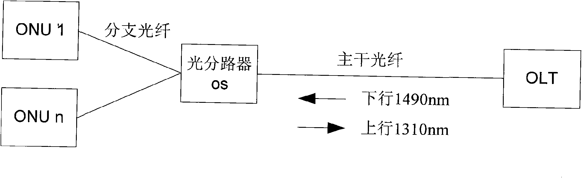
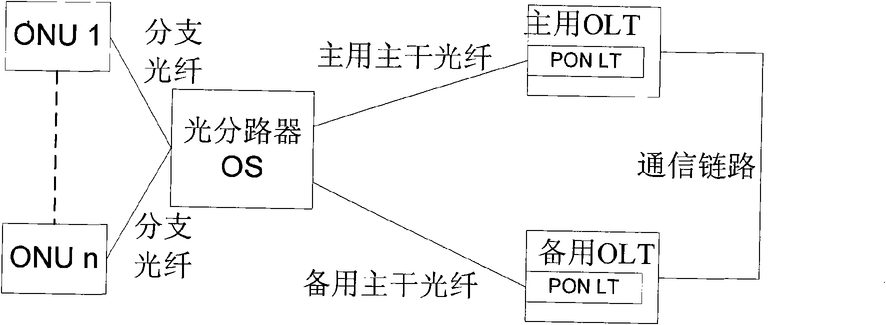
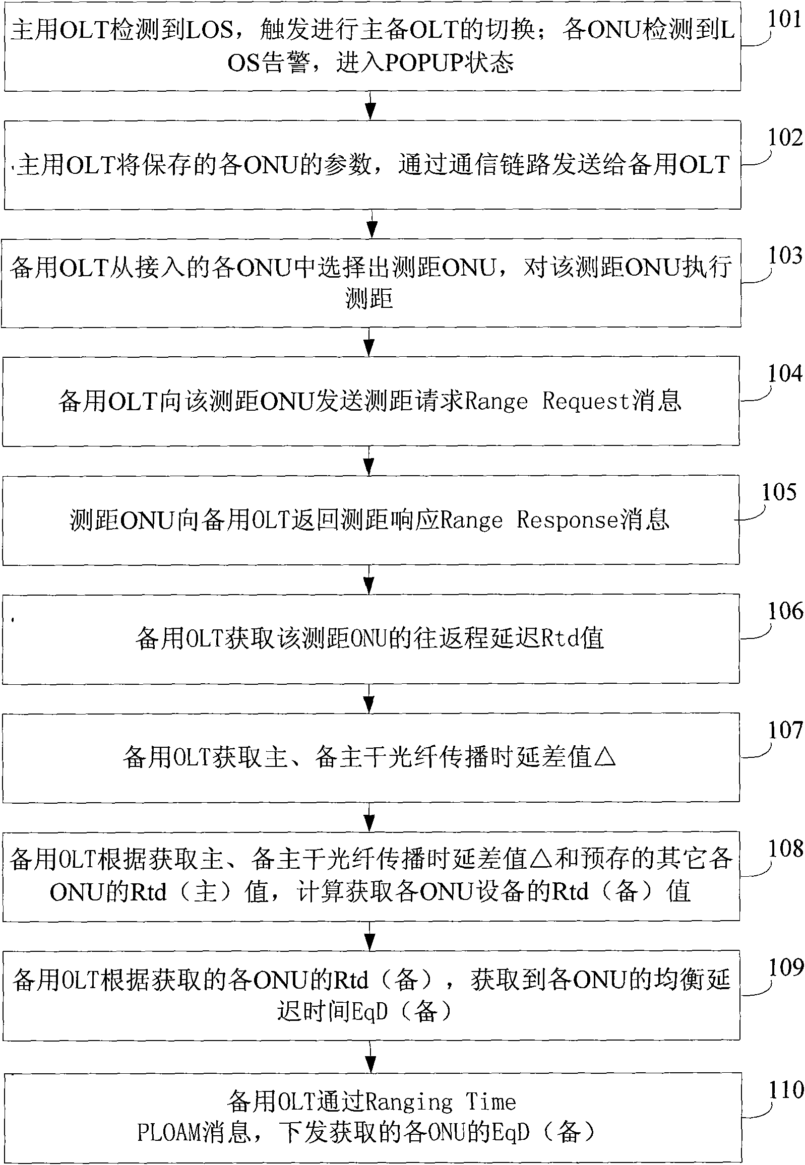
[0059] When the main optical fiber of the main OLT in the PON network fails (or the main OLT fails), the PON network needs to perform active-standby switching to switch data to the standby OLT. This embodiment takes figure 2 The schematic diagram of active / standby switchover is provided as an example. During the switchover process of the active / standby OLT, due to the different parameters such as the length of the active trunk fiber and the backup trunk fiber, the standby OLT, that is, the new active OLT, needs to connect The ONU performs ranging processing again. In order to reduce the ranging time required for performing ranging processing on all connected ONUs and reduce service interruption time, the embodiment of the present invention provides a method for sending data through an optical network. see image 3 , in this embodiment, the main optical fiber of the active OLT fails and needs to perform active-standby switchover as an example for illustration. The content of...
Embodiment 2
[0098] In the PON network, due to the switchover of the active and standby OLTs due to the failure of the main fiber, each ONU needs to obtain a new EqD value due to the difference in parameters such as the length of the main and standby main fibers. Figure 5 , an embodiment of the present invention provides a system for sending data over an optical network, the system includes: a sending device, a distance measuring device, and a non-distance measuring device, wherein,
[0099] The sending device is used to obtain the first round-trip delay Rtd value of the ranging device and the non-ranging device; it is also used to send a ranging request to the ranging device, and obtain the second value of the ranging device according to the ranging response of the ranging device. The round-trip delay Rtd value; according to the first Rtd value and the second Rtd value of the ranging device, obtain the change value of the Rtd value; when the change value is obtained, according to the chan...
Embodiment 3
[0120] see Figure 7 , an embodiment of the present invention provides a device for sending data through an optical network, the device includes:
[0121] Obtaining module, for obtaining the first round-trip delay Rtd value (being the Rtd value on the active OLT) of ranging equipment and non-ranging equipment;
[0122] The ranging module is used to send a ranging request to the ranging device, and obtains the second round-trip delay Rtd value (that is, the Rtd value on the standby OLT) of the ranging device according to the ranging response of the ranging device;
[0123] The difference module is used to obtain the change value of the Rtd value according to the first Rtd value of the ranging device obtained by the obtaining module and the second Rtd value of the ranging device obtained by the ranging module;
[0124] A processing module, configured to obtain the second Rtd value of the non-ranging device according to the change value obtained by the difference module and the ...
PUM
 Abstract
Description
Claims
Application Information
PatSnap Eureka turns technology decisions into work you can execute. Powered by our Innovation Knowledge Graph, it runs expert workflows across engineering, life sciences, materials and intellectual property. Get your review-ready output in minutes.


