
Dual-screen digital radiographic imaging detector array

An imaging array, X-ray technology, used in radiation measurement, X-ray/infrared technology, instruments for radiological diagnosis, etc. The effect of reducing the ray absorption loss

Active Publication Date: 2009-10-21
CARESTREAM HEALTH INC
View PDF10 Cites 39 Cited by
  • Summary
  • Abstract
  • Description
  • Claims
  • Application Information

AI Technical Summary

Problems solved by technology

[0002] Typically, medical X-ray detectors that employ scintillation phosphor screens to absorb X-rays and generate light suffer from a loss of spatial resolution due to the lateral light diffusion of the screen

Method used


Image

  • Dual-screen digital radiographic imaging detector array
  • Dual-screen digital radiographic imaging detector array
  • Dual-screen digital radiographic imaging detector array

Examples


Embodiment Construction

[0054] Reference is made to commonly assigned, pending examination (a) U.S. Patent Application No. 1, filed July 14, 2006 by Yorkston et al. 11 / 487,539; and (b) US Patent Application No. 12 / 025,086, entitled "DIGITAL RADIOGRAPHIC IMAGING APPARATUS," filed February 4, 2008 by Tredwell.

[0055] The description is particularly directed to elements which form part of, or co-operate more directly with, the device of the invention. It should be understood that each element not particularly shown or described may take various forms well known to those skilled in the art. In the following description, terms and phrases such as "above" or "upper" are used in a broad sense to give the configuration of the various layers relative to each other. The x-ray imaging disk can of course be exposed in any azimuth orientation, where the layers of the stack generally extend in a horizontal, vertical, or oblique direction.

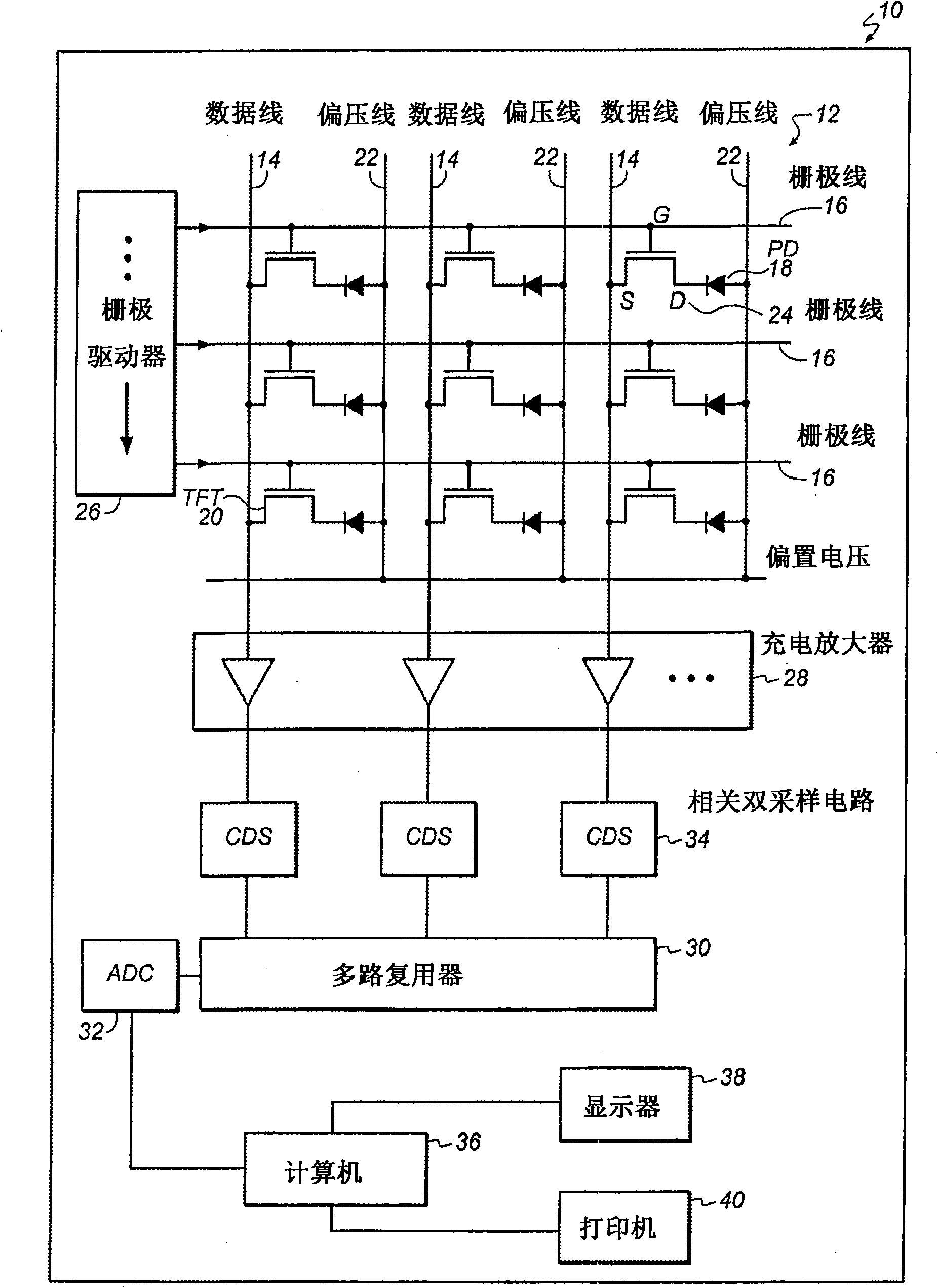
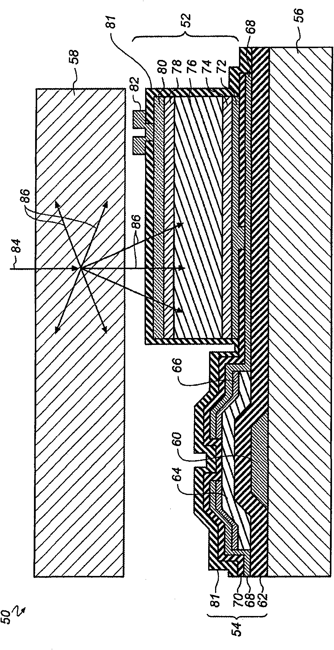
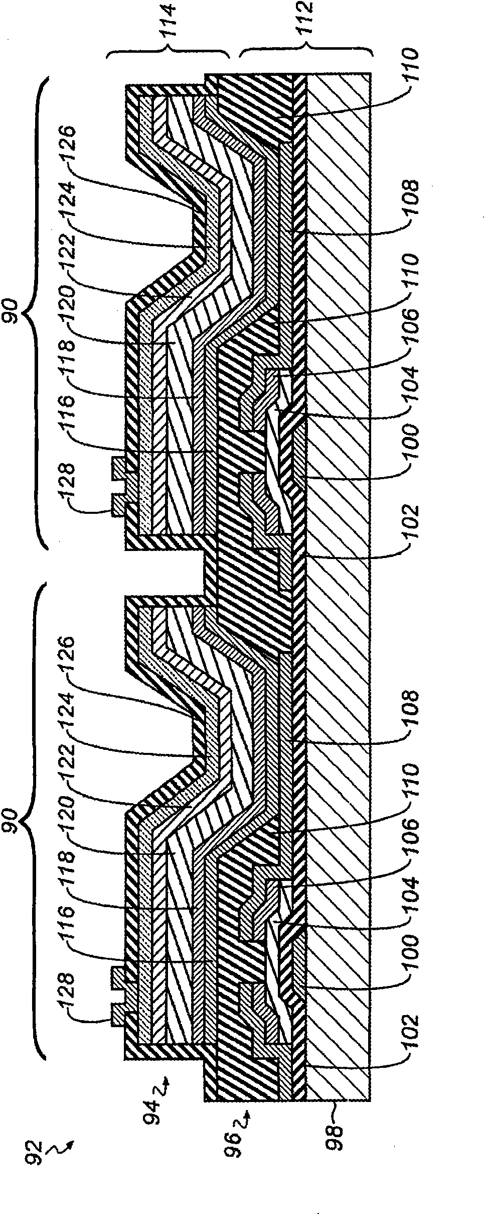
[0056] Figure 5 to Figure 17 Schematic diagrams showing various digi...


PUM


Abstract

A radiographic imaging device has a first scintillating phosphor screen having a first thickness and a second scintillating phosphor screen having a second thickness. A transparent substrate is disposed between the first and second screens. An imaging array formed on a side of the substrate includes multiple photosensors and an array of readout elements.

Description

technical field [0001] The present invention relates generally to digital radiography and, more particularly, to the use of dual, asymmetric phosphor screens in digital radiography flat panel imaging detector arrays to improve image quality. Background technique [0002] Typically, medical X-ray detectors that employ scintillation phosphor screens to absorb X-rays and generate light suffer from a loss of spatial resolution due to the lateral light diffusion of the screen. In order to reduce lateral light diffusion and maintain acceptable spatial resolution, the phosphor screen must be made sufficiently thin. The spatial resolution and X-ray detection capabilities of imaging devices are often characterized by the modulation transfer function (MTF) and X-ray absorption efficiency, respectively. Thin phosphor screens yield better MTF at the expense of reduced X-ray absorption. Typically, the coating density and thickness of the phosphor screen are designed as a compromise bet...

Claims


Application Information

Patent Timeline
Patent Type & Authority Applications(China)
IPC IPC(8): G01T1/20H01L27/146G21K4/00A61B6/00H01L27/14H04N5/32
CPCH01L27/14636G21K4/00G01T1/2018G21K2004/04H01L27/14632H01L27/14663H01L27/1464G01T1/20183G01T1/20181G01T1/20A61B6/00H04N5/32H01L27/14
Inventor T·J·特雷威尔R·S·克尔R·W·库尔平斯基J·约克斯顿T·J·沃奇克K·-L·叶
Owner CARESTREAM HEALTH INC
Learn More