Negative pressure magnetic stirring concentrator

A technology of magnetic stirring and concentrator, which is applied in the field of concentrator, can solve the problems of wasting high-purity nitrogen, polluting air, easy leakage cost, etc., and achieve the effect of reducing concentration time, reducing pollution and low manufacturing cost

Inactive Publication Date: 2009-10-28
NORTHEAST INST OF GEOGRAPHY & AGRIECOLOGY C A S
View PDF0 Cites 11 Cited by
  • Summary
  • Abstract
  • Description
  • Claims
  • Application Information

AI Technical Summary

Problems solved by technology

[0004] The purpose of the present invention is to provide a negative pressure magnetic stirring concentrator to solve the problems of high cost of gas leakage at the rotating shaft of the rotary evaporator to concentrate the liquid, waste of high-purity nitrogen and pollute the air by using a nitrogen blower to concentrate the liquid

Method used


Image

  • Negative pressure magnetic stirring concentrator

Examples


specific Embodiment approach 1

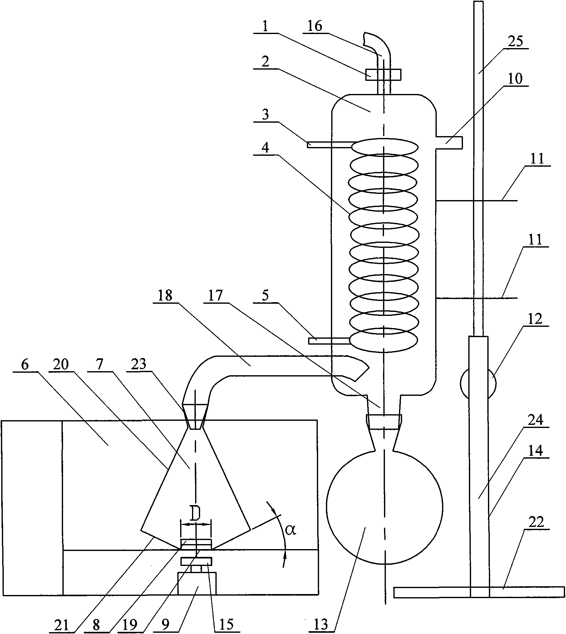
[0008] Specific implementation mode one: combine figure 1 Describe this embodiment, the concentrator of this embodiment is made up of magnetic stirring water bath heating device, vacuum condensing device, solvent recovery bottle 13, concentration bottle 7, lifting support 14, two fixing clips 11 and connecting pipe 18; The water bath heating device is composed of a constant temperature water bath pot 6, a magnetic rod 8 with a polytetrafluoroethylene jacket, a long magnet 15 and a motor 9, and the vacuum condensing device is composed of a pressure reducing valve 1, a vacuum chamber 2 and a condensate coil 4 The vacuum chamber 2 is fixedly connected with the lifting bracket 14 by two fixing clips 11, and the condensed water coil 4 is housed in the vacuum chamber 2, one end of the condensed water outlet 3 of the condensed water coil 4 and the condensed water inlet 5 One end is respectively exposed outside through the side wall of the vacuum chamber 2, and the condensed water out...

specific Embodiment approach 2

[0009] Specific implementation mode two: combination figure 1 Describe this embodiment, the bottleneck 23 of the concentration bottle 7 described in this embodiment is gradually reduced in diameter from top to bottom, and the shape of the bottle body of the concentration bottle 7 is gradually reduced by the upper circular platform body 20 and the diameter of the diameter gradually increasing from top to bottom. The lower round platform body 21 is formed, and the diameter of the concentrated bottle bottom 19 is 2cm~4cm, and the angle α between the side wall of the lower round platform body 21 of the concentrated bottle 7 and the horizontal plane is 14°~16°. Such setting can increase the interface area between the gas and liquid phases and speed up the volatilization rate of the solvent. Others are the same as in the first embodiment.

specific Embodiment approach 3

[0010] Specific implementation mode three: combination figure 1 Describe this embodiment, the diameter of the concentrated bottle bottom 19 described in this embodiment is 3cm, and the included angle α between the side wall of the lower circular table body 21 of the concentrated bottle 7 and the horizontal plane is 15°. Such setting can increase the interface area between the gas and liquid phases and speed up the volatilization rate of the solvent. Others are the same as in the second embodiment.


PUM

PropertyMeasurementUnit
diameteraaaaaaaaaa

Abstract

A negative pressure magnetic stirring concentrator relates to a concentrator and aims at solving the problems that air leaks easily at a rotating shaft, the preparation cost is high when adopting a rotary evaporator to concentrate liquid, and high purity nitrogen is wasted, air is polluted when adopting a pressure blowing concentrator to concentrate liquid, etc. A vacuum chamber is fixedly connected with a lifting support through two retaining clips, internally provided with a condense water coiled tube and provided with a pumping hole connected with a vacuum pump thereof, the upper end of the vacuum chamber is provided with a reducing valve and the lower end thereof is provided with a solution recovering bottle, two ends of a connecting tube are communicated with the vacuum chamber and a concentrating bottle that is arranged at the bottom of a thermostat water bath, a bar magnet externally coated with polyfluortetraethylene is arranged in the concentrating bottle, an electric motor is fixedly arranged below the bottom of the thermostat water bath, and an output shaft of the electric motor is connected with the lower end surface of a long-strip magnet, the upper end surface of which is magnetically connected with the lower end surface of the bar magnet externally coated with polyfluortetraethylene. The concentrator has the advantages of good air tightness, low preparation cost, no need of consuming high purity nitrogen and light environment pollution.

Description

technical field [0001] The invention relates to a concentrator. Background technique [0002] Liquid concentrators are commonly used in the analysis of organic components in organisms, water, soil, and some products. At present, the commonly used concentration devices include rotary evaporator and nitrogen blowing device. The operation process of the rotary evaporator is mainly to place the glass container filled with liquid obliquely in the constant temperature water bath, the motor drives the glass container to rotate through the deceleration device, and uses a vacuum pump to evacuate the solvent to vaporize the solvent at a lower temperature, so as to achieve concentration. the goal of. This method has the advantages of simple structure, convenient operation, and the evaporated liquid can be recovered after condensation. The disadvantages are that the shaft is prone to air leakage, the preparation cost is relatively high, and only one sample can be concentrated at a tim...

Claims


Application Information

Patent Timeline
Patent Type & Authority Applications(China)
IPC IPC(8): B01L3/00G01N1/40B01D1/00
Inventor 王健
Owner NORTHEAST INST OF GEOGRAPHY & AGRIECOLOGY C A S
Why Eureka
Try Eureka