Air cleaning single region electronic dust-collecting unit

An air purification, single-zone technology, applied in the direction of electrode structure, electrostatic separation, etc., can solve the problems of air velocity limitation in dust collection area, application field limitation, deformation of electrode plate in dust collection area, etc. Simple, low cost effect

Inactive Publication Date: 2009-10-28
深圳市电精科技有限公司
View PDF0 Cites 6 Cited by
  • Summary
  • Abstract
  • Description
  • Claims
  • Application Information

AI Technical Summary

Problems solved by technology

[0004] ① The two-zone electronic dust collection unit has the characteristics of high efficiency and large dust collection capacity, but because the dust collection plate is placed parallel to the airflow direction, the effective driving speed of the charged dust particles and the trajectory of the charged dust particles The limitation of the airflow velocity in the dust collection area is strictly limited
[0005] ②The positive and negative poles placed in parallel in the dust collection area of ​​the two-zone electronic dust collection unit are fastened together through series tubes. Plates are prone to deformation
[0006] ③ The material and production costs of the two-zone electronic dust collection unit are relatively high, and its application field is limited to a certain extent

Method used


Image

  • Air cleaning single region electronic dust-collecting unit
  • Air cleaning single region electronic dust-collecting unit

Examples


Embodiment

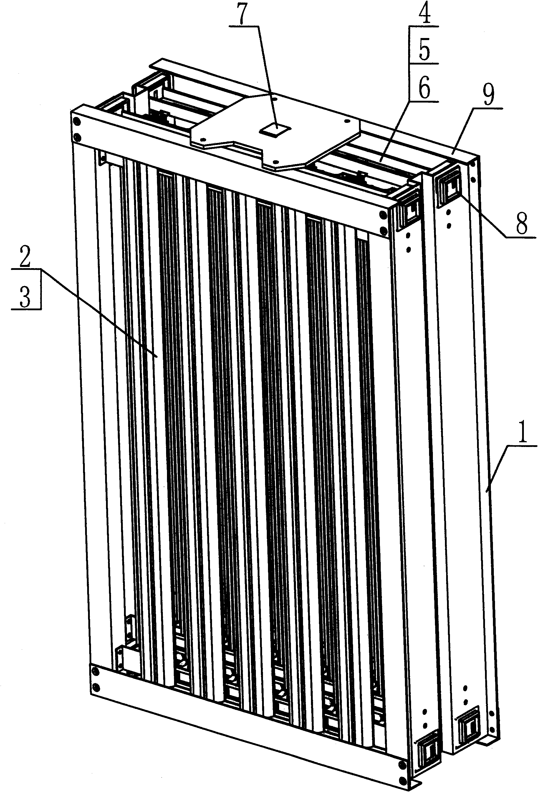
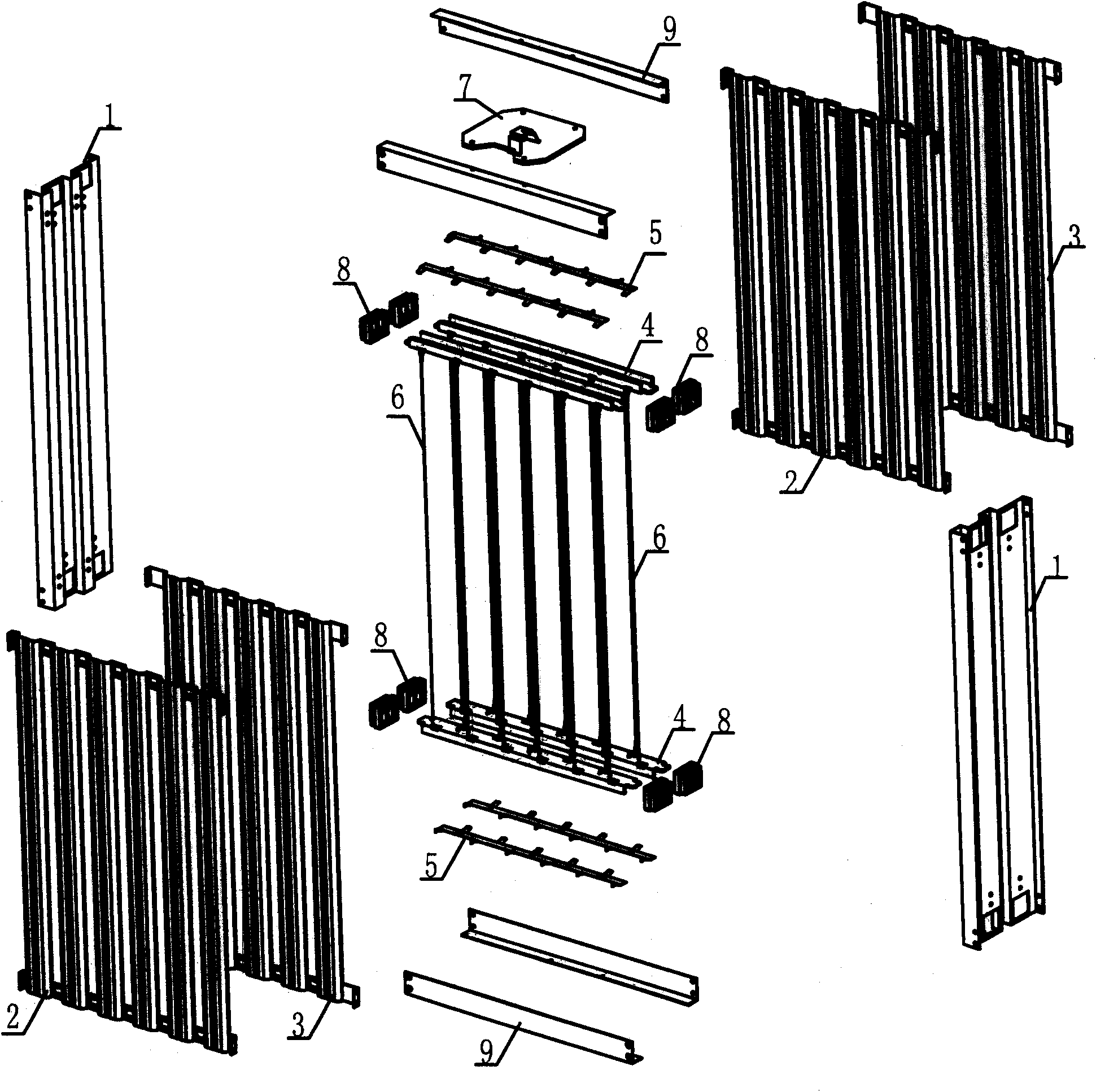
[0019] Example: from figure 1 with figure 2 It can be clearly seen that the single-zone electronic dust collection unit is composed of side plate 1, dust collection plate A 2, dust collection plate B 3, electrode beam 4, electrode spring hook 5, electric line 6, electrode contact plate 7, Insulating pad 8 and beam 9 are formed.

[0020] The assembly relationship is as follows:

[0021] ①Insert the electrode spring hook 5 on the electrode beam 4 first, and then insert two insulating pads 8 on both ends of the electrode beam 4.

[0022] ②Insert multiple electrode beams 4 prepared according to the above ① into the two side plates 1 through the relevant holes in the side plates 1 respectively.

[0023] ③Insert the dust collecting board A2 and the dust collecting board B3 into the specified positions between the two side boards 1, and fix them on the side board 1 with rivets.

[0024] ④ Use four beams 9 to rivet the two side plates 1 into one.

[0025] 5. The electric wire 6 ...


PUM


Abstract

The invention relates to an air cleaning electronic dust-removing device which comprises a single region electronic dust-collecting unit that consists of corona electrodes and w-shaped dust-collecting plates and integrates dust particle charge and collection function. The dust-collecting unit is formed by a plurality of corona electrodes and w-shaped dust-collecting plates which are multi-distributed on a vertical surface of the airflow direction. The air cleaning electronic dust-removing device is characterized in that the w-shaped dust-collecting plates are multi-distributed on the vertical surface of the airflow direction against the wind, thereby improving the speed of the charge dust particles moving towards the dust-collecting plates, prolonging the movement track of the dust particles in a dust-collecting region, and realizing the miniaturization of the dust-collecting unit under the conditions of same input air and efficiency. The air cleaning electronic dust-removing device is also characterized in that high dust-collecting efficiency is always kept under high airflow speed, thereby being suitable to be arranged in environment with high airflow speed. Moreover, the air cleaning electronic dust-removing device is characterized by having convenient manufacture and less operation and maintenance cost. The air cleaning electronic dust-removing device has the advantages of high processing wind speed, good dust-collecting effect, large dust-collecting amount, low power consumption, and less operation and maintenance cost, can be used for cleaning air with dust diameter not less than 0.3 micrometer and wind speed reaching up to 4m / s under the matching of a rated electric field and can achieve the one-time cleaning efficiency of 90 percent.

Description

[technical field] [0001] The invention relates to an air purification device, in particular to a single-zone electronic dust collection room for air purification with high efficiency and large air volume. [technical background] [0002] At present, the dust collection unit of the electronic dust removal device for air purification mostly adopts the two-zone electronic dust collection unit, and the single-zone dust collection unit is rarely used in the large air volume air treatment device due to its low efficiency and small dust collection capacity. Adopted. [0003] The disadvantages of the two-zone dust collection device are: [0004] ① The two-zone electronic dust collection unit has the characteristics of high efficiency and large dust collection capacity, but because the dust collection plate is placed parallel to the airflow direction, the effective driving speed of the charged dust particles and the trajectory of the charged dust particles The airflow velocity in th...

Claims


Application Information

Patent Timeline
Patent Type & Authority Applications(China)
IPC IPC(8): B03C3/40B03C3/47
Inventor 李白镛
Owner 深圳市电精科技有限公司
Why Eureka
Try Eureka