
Advanced nitrogen and phosphorus removal device and process control method thereof

A technology for deep denitrification and nitrate nitrogen, applied in chemical instruments and methods, multi-stage water/sewage treatment, water/sludge/sewage treatment, etc., can solve the problem of complex pipeline layout, high energy consumption, and insufficient utilization Raw water carbon source and other issues, achieve the effects of simple control loop, saving operating costs, and improving the denitrification potential of the system

Active Publication Date: 2011-04-20
BEIJING UNIV OF TECH
View PDF0 Cites 0 Cited by
  • Summary
  • Abstract
  • Description
  • Claims
  • Application Information

AI Technical Summary

Problems solved by technology

However, with the rapid development of water treatment technology and increasingly stringent discharge standards, the actual operation process has gradually exposed the inverted A 2 Disadvantages of the / O process: ①Since the process involves two return pipelines, the energy consumption is large and the pipeline layout is complicated
②Unable to make full use of raw water carbon source
There have been a lot of reports on the process control and operation optimization of sewage treatment plants in foreign countries, but there are few domestic studies on the process control of activated sludge process, which are generally limited to the simulation of mathematical models, and the simulation process is only for specific water quality and process. optimization, and even less process control research on continuous flow processes

Method used


Image

  • Advanced nitrogen and phosphorus removal device and process control method thereof
  • Advanced nitrogen and phosphorus removal device and process control method thereof
  • Advanced nitrogen and phosphorus removal device and process control method thereof

Examples


Embodiment Construction

[0027] Below in conjunction with accompanying drawing and embodiment describe the patent of the present invention in detail:

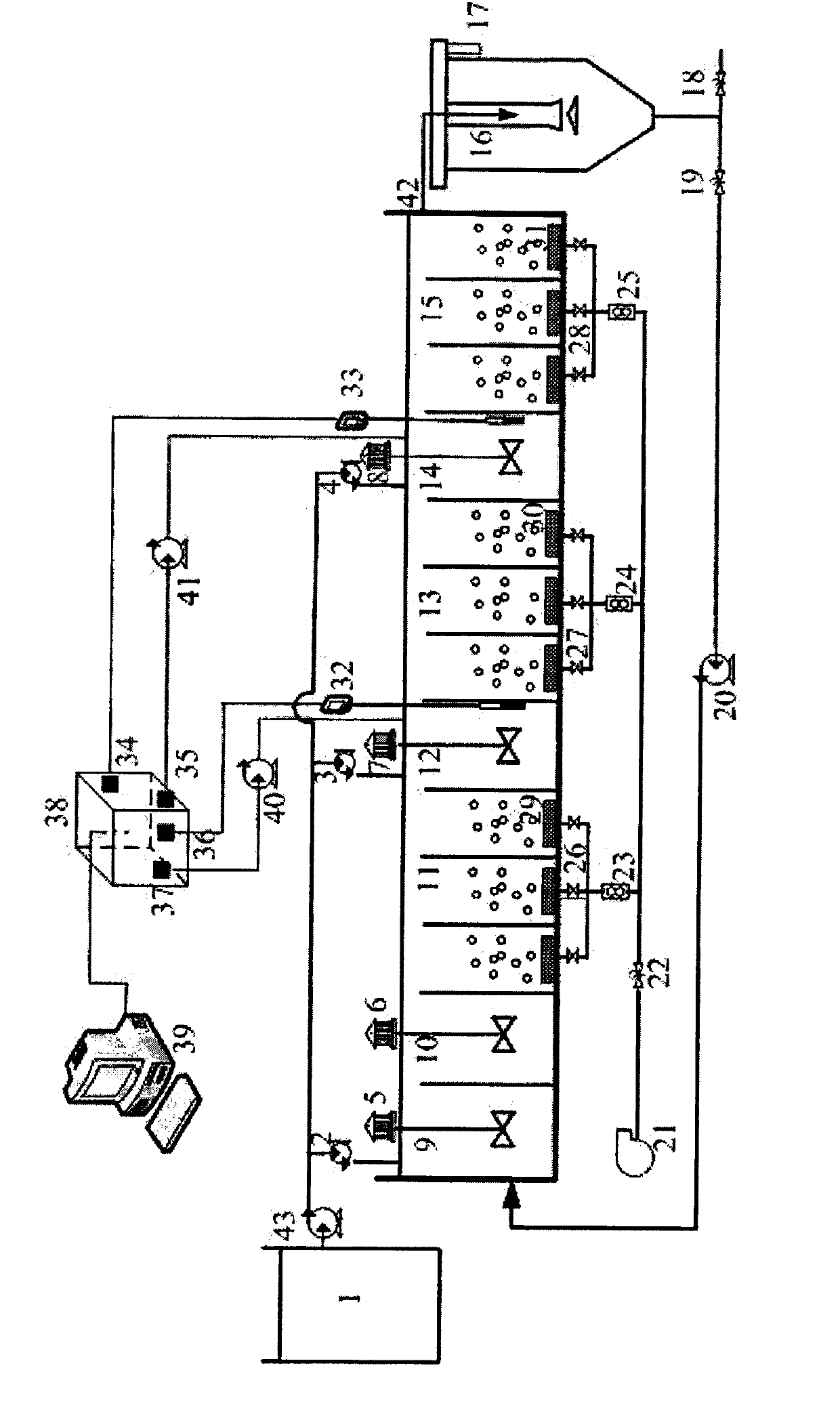
[0028] Such as figure 1 As shown, a deep denitrification and phosphorus removal device, wherein the sewage water tank 1 is connected with the main water inlet pump 43, and the water outlet of the main water inlet pump 43 is divided into three parts, which pass through the first section of water inlet pump 2, the second section of water inlet pump 3 and The third section water inlet pump 4 enters the main body bioreactor, and the sewage water tank 1, the total water inlet pump 43, the first section water inlet pump 2, the second section water inlet pump 3, the third section water inlet pump 4 and the main body bioreactor pass through the water inlet pump 4 and the main body bioreactor. The water pipes are connected, the main bioreactor enters the sedimentation tank 16 through the water outlet 42, and part of the sludge in the sedimentation tank 16 is re...


PUM


Abstract

The invention relates to an advanced nitrogen and phosphorus removal device and a process control method thereof, belonging to the technical field of biological sewage treatment by using a biochemical method. Aiming at the defects that the existing A / O step feed technology can not synchronously have advanced biological phosphorus removal, reverse A<2> / O technology is high in energy consumption and complicated in operation and the like, the invention combines the reverse A<2> / O technology and the step feed technology, nitrification liquid internal reflux does not needed to be set, a first section is provided with an anaerobic reactor, anoxic reactors at a second section and a third section are respectively installed on an ORP on-line sensor and a nitrate on-line sensor, and data obtained by collecting ORP and nitrate in an on-line way can be taken as input of a process controller, is output by fuzzification treatment and can act on opening and closing a frequency converter of an actuating mechanism and an external carbon source dosing metering pump so as to save the external carbon dosage. The invention can greatly improve the denitrification effect of the step feed technology, utilizes carbon source of raw water to the utmost extent, realizes synchronous nitrogen and phosphorus removal, and has the advantages of simple control structure and stable quality of yielding water.

Description

technical field [0001] The invention relates to a deep denitrification and dephosphorization device and a process control method, especially an improved inverted A 2 The / O segmented influent deep nitrogen and phosphorus removal device and process optimization control technology belong to the field of biochemical sewage biological treatment and automatic control theory technology, and are suitable for deep nitrogen and phosphorus removal of domestic sewage and industrial wastewater in large, medium and small cities. Background technique [0002] In the "Pollutant Discharge Standards for Urban Sewage Treatment Plants" (GB18918-2002) promulgated in 2002, my country requires that the effluent quality of all sewage units should be less than 5m / L for ammonia nitrogen, less than 15m / L for total nitrogen, and less than 0.5m / L for total phosphorus ( Level A standard), it can be seen that the removal of nitrogen and phosphorus pollutants has become the main problem of sewage treatment...

Claims


Application Information

Patent Timeline
Patent Type & Authority Patents(China)
IPC IPC(8): C02F9/14
Inventor 王淑莹葛士建彭永臻
Owner BEIJING UNIV OF TECH
Learn More