
Copper cooling plate and manufacturing process thereof

A technology of copper cooling plate and body, applied in the direction of cooling devices, etc., can solve the problems of large interface thermal resistance, affecting heat transfer efficiency, weld cracking, etc., and achieve the effect of increasing the heat dissipation area and increasing the heat dissipation area

Inactive Publication Date: 2009-11-04
XI AN JIAOTONG UNIV
View PDF0 Cites 7 Cited by
  • Summary
  • Abstract
  • Description
  • Claims
  • Application Information

AI Technical Summary

Problems solved by technology

[0002] Copper cooling plates and copper cooling staves replace cast steel and cast iron cooling staves with excellent thermal conductivity and are widely used in the furnace body structure of modern large-scale blast furnaces. The heat dissipation area of ​​the water channel in the inner cavity is small, and most of them are manufactured by casting process. Although it has the advantage of integral molding, due to the low material density of the normal pressure casting, the high thermal conductivity of copper cannot be fully utilized.
In addition, the shape accuracy of castings is low, and it cannot be closely built with high-precision refractory bricks, resulting in a large thermal resistance at the interface between the two, which affects heat transfer efficiency.
At the same time, in order to weld and install the copper cooling plate on the steel shell of the blast furnace shell, a ring of steel ring or steel strip is usually welded at one end of the copper cooling plate. During the process, weld cracking and gas leakage in the furnace are prone to occur.
[0003] Foreign companies have adopted the form of integral casting to improve the shape accuracy through machining so as to facilitate the compact masonry of furnace wall refractory bricks, but there are still low density of casting materials and other problems mentioned above

Method used


Image

  • Copper cooling plate and manufacturing process thereof
  • Copper cooling plate and manufacturing process thereof
  • Copper cooling plate and manufacturing process thereof

Examples


Embodiment Construction

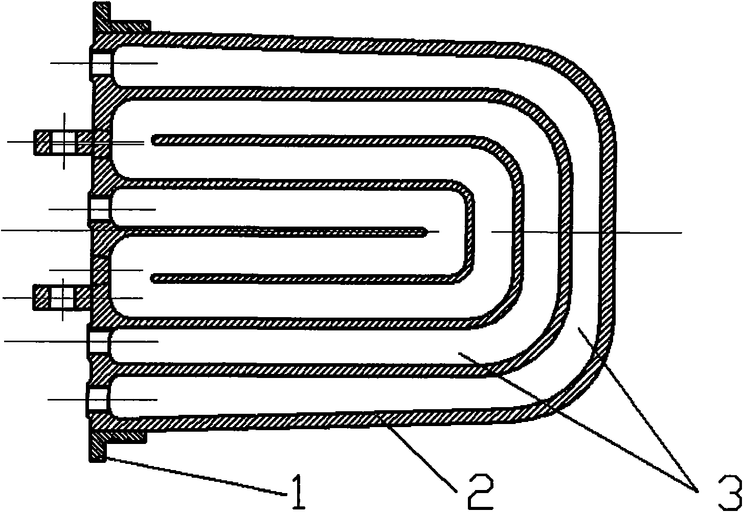
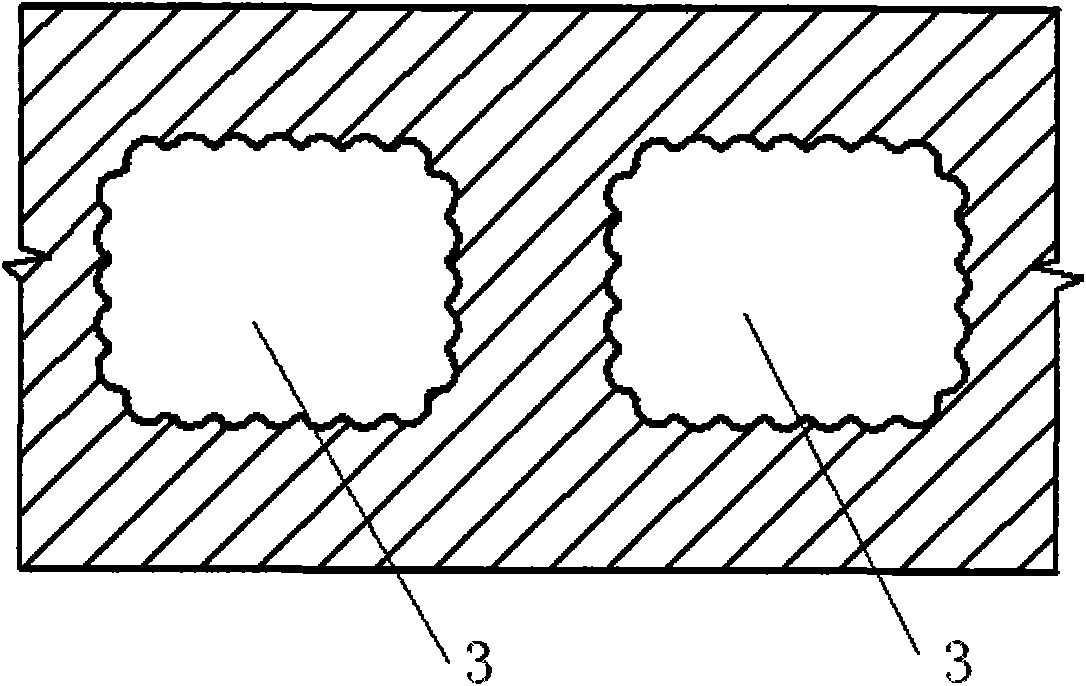
[0021] refer to figure 1 , figure 2 , image 3 As shown, one end of the copper body 2 is wrapped with a steel strip or a steel ring 1, and the inner water channel 3 is arranged inside the copper body 2, and the outer edge of the section of the inner water channel 3 is curved. The curve shape of the outer edge of the cross-section of the inner cavity water channel 3 is a plum petal shape or a tooth shape that can increase the heat dissipation area of ​​the inner surface of the inner cavity water channel. The entire connecting surface of the copper body 2 and the steel strip or steel ring is fused together. The connecting surface is in tooth shape or concave-convex shape that can increase mechanical engagement.

[0022] The novel copper cooling plate of the present invention is manufactured by a liquid die forging process and integrally formed, and its material density, thermal conductivity, shape precision, and mechanical properties are all significantly improved compared w...


PUM


Abstract

The invention relates to a copper cooling plate and a manufacturing process thereof. The outer edge of the cross section of an inner cavity water way has a curved shape or a plum blossom petal shape, and a steel belt or a steel ring contact surface for mounting the copper cooling plate has a tooth shape. The process comprises the following steps: using a spraying gun to evenly spray a graphite paint on the die cavity inner surface or a die core surface of a die, fixing the steel ring or the steel belt prefabricated with the tooth shape on the inner surface in the die, and preheating the die, the die core and the steel belt or the steel ring until the temperature is between 150 and 400 DEG C; pouring molten copper into the die; closing and pressurizing the die and keeping the pressure with a specific pressure of between 50 and 300 MPa; opening the die to take out the coagulated and formed copper cooling plate; and drawing out steel wire inner cores one by one from the coagulated and formed copper cooling plate, and performing mechanical processing to remove the excess part of the appearance of the copper cooling plate. The copper cooling plate is manufactured by adopting a liquid forging process method, thus the material density, the heat conductivity factor, the appearance precision and the mechanical property are greatly improved, and simultaneously, the characteristic of integral molding is kept.

Description

technical field [0001] The invention relates to the preparation of cooling equipment for a furnace body of an ironmaking blast furnace, in particular to a novel copper cooling plate and a manufacturing process. Background technique [0002] Copper cooling plates and copper cooling staves replace cast steel and cast iron cooling staves with excellent thermal conductivity and are widely used in the furnace body structure of modern large-scale blast furnaces. Shaped, the heat dissipation area of ​​the inner cavity water channel is small, and most of them are manufactured by casting technology. Although it has the advantage of integral molding, due to the low material density of atmospheric castings, the high thermal conductivity of copper cannot be fully utilized. In addition, the shape accuracy of the casting is low, and it cannot be closely built with the high-precision processed refractory bricks, resulting in a large thermal resistance at the interface between the two, whic...

Claims


Application Information

Patent Timeline
IPC IPC(8): C21B7/10B22D19/16
Inventor 于德弘周嘉平
Owner XI AN JIAOTONG UNIV
Learn More