Split type reaming bit for large-diameter raising-boring and assembly method thereof

A reaming bit, large-diameter technology, used in drill bits, drilling equipment, drill pipes, etc.

Inactive Publication Date: 2009-11-04
BEIJING CHINA COAL MINE ENG CO LTD
View PDF0 Cites 17 Cited by
  • Summary
  • Abstract
  • Description
  • Claims
  • Application Information

AI Technical Summary

Problems solved by technology

[0003] The main purpose of the present invention is a split-type large-diameter back-hole drilling reaming bit developed to solve the limitation of the narrow chamber of the underground transportation roadway in coal mines.

Method used


Image

  • Split type reaming bit for large-diameter raising-boring and assembly method thereof
  • Split type reaming bit for large-diameter raising-boring and assembly method thereof
  • Split type reaming bit for large-diameter raising-boring and assembly method thereof

Examples


Embodiment Construction

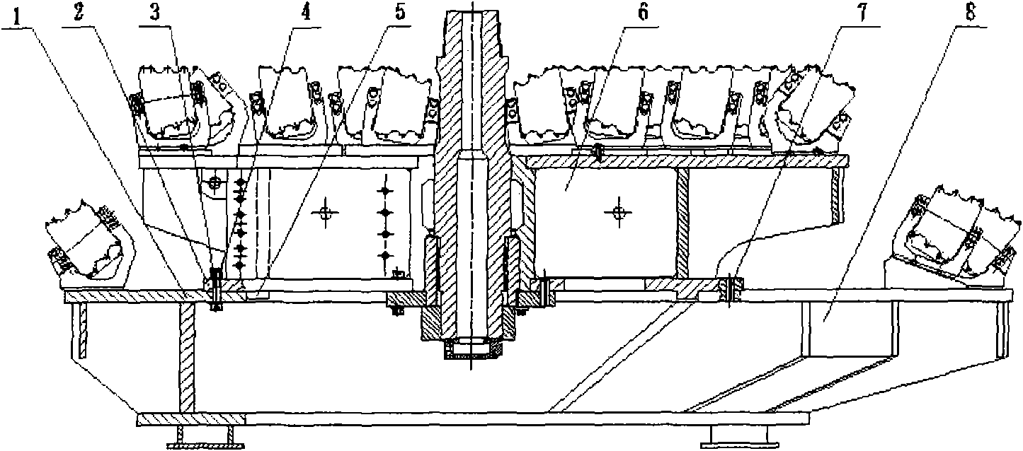
[0014] Such as figure 1 Shown, the present invention is that the first-stage reaming bit body 6 of 3.5m by the reaming diameter that is positioned at the upper part cooperates with the second-stage reaming drill extension part 8 that the reaming diameter is 5.0m through its lower branch, The upper panel 1 of the expansion part of the second-stage reaming drill is connected with the lower panel 2 of the first-stage reaming drill with bolts 3, lock nuts 4 and positioning pins 7 to form the overall structure of the large-diameter reaming drill, which constitutes The "tower" structure formed by the first stage reaming drill 6 and the second stage reaming drill positioned at its lower part.

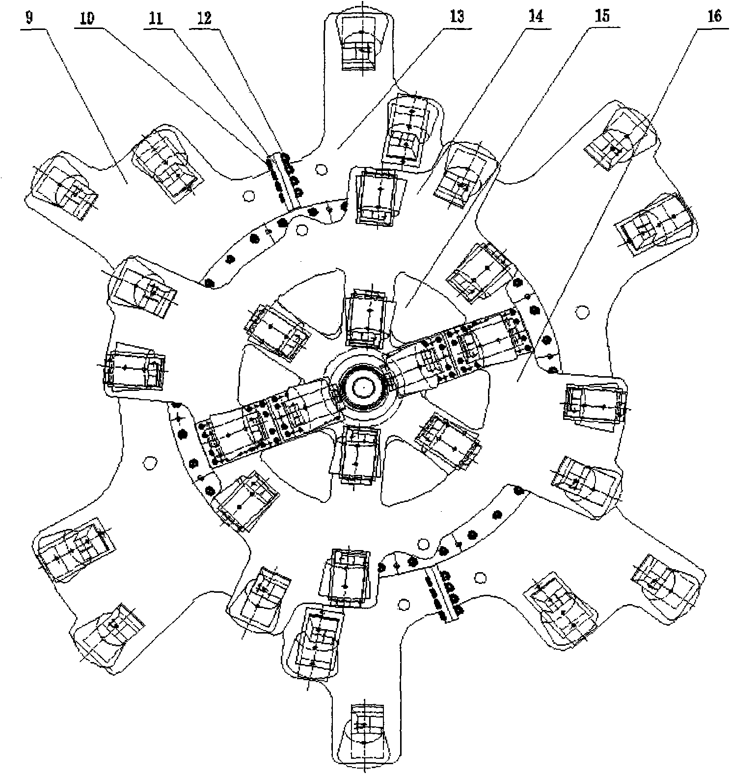
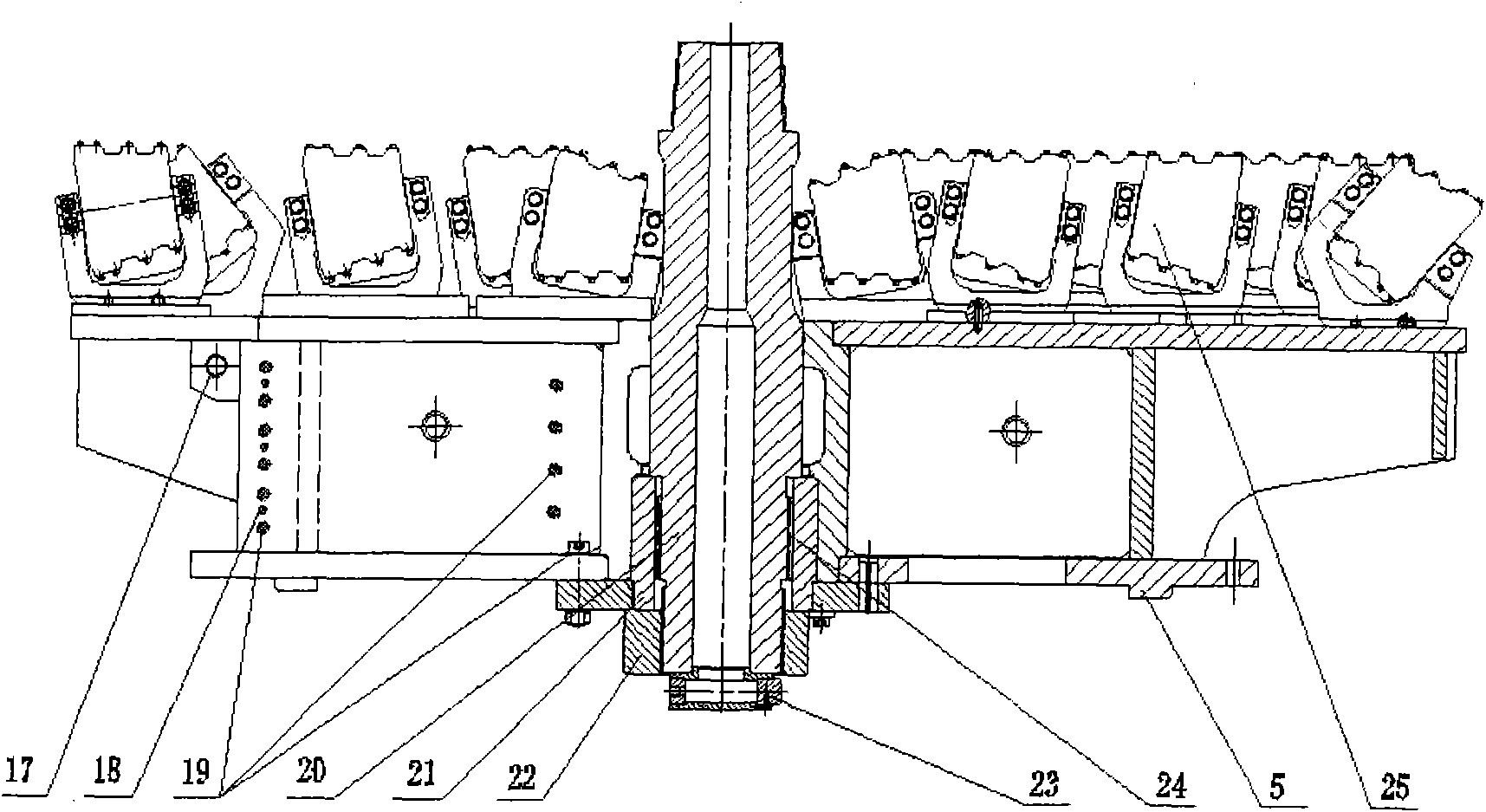
[0015] refer to Figure 2 to Figure 4 , wherein the upper first-stage reaming bit body 6 is divided into left and right halves 14, 16, and the left and right halves 14 and 16 pass through longitudinal positioning pins 18, bolts 19 and transverse connecting bolts 27 and positioning The pins 2...


PUM


Abstract

The invention relates to a split type reaming bit for large-diameter raising-boring used in mining machinery and an assembly method thereof. The reaming bit for large-diameter raising-boring is of a split type structure by which the bit is split and transport dimension and weight of the bit are controlled after disassembly, which solves the difficulty of transport and assembly in a narrow roadway of a coal mine, and the reaming bit has higher stability and higher reliability under combined action of great torque, tension and impact.

Description

technical field [0001] The invention relates to a drill bit in mining mechanical equipment, in particular to a split-type reaming drill bit for large-diameter back-hole drilling. Background technique [0002] Coal mine safety production is an important research topic. To solve the problem of coal mine safety production, it is necessary to increase shaft construction methods such as coal mine ventilation shafts and gas drainage shafts. In the prior art, shaft excavation mainly includes manual blasting excavation method, freezing method, grouting method, drilling method and other operation methods, but these methods have long operation period and low economic benefits. At present, the raised well drilling method has been widely used in the construction of shafts with lower transportation roadways and stable geological conditions. This method has a short operation period, low labor intensity, safety and reliability, and good economic and social benefits. However, the existing r...

Claims


Application Information

Patent Timeline
Patent Type & Authority Applications(China)
IPC IPC(8): E21B10/26E21B10/32E21B19/18
Inventor 刘志强武士杰张广宇刘日辉孙建荣汪船程守业
Owner BEIJING CHINA COAL MINE ENG CO LTD
Why Eureka
Try Eureka