High-pressure compressing solid-liquid separation device of flexible pipe

A solid-liquid separation and high-pressure technology, which is applied in the direction of filtration separation, separation method, fixed filter element filter, etc., can solve the problems of restricting the popularization and use of solid-liquid separation devices, high manufacturing cost, and long axial length of the filter tube unit.

Inactive Publication Date: 2009-11-11
张民良
View PDF2 Cites 14 Cited by
  • Summary
  • Abstract
  • Description
  • Claims
  • Application Information

AI Technical Summary

Problems solved by technology

[0002] In the existing flexible tube high-pressure press solid-liquid separation device, for example, in the "flexible tube filter" application number 200420092669.X, "flexible tube filter" application number 2004100779750, the known technology adopts the tubular grid design In this scheme, the stress is relatively large when the filter chamber is deformed under pressure, so the lead axis of the filter tube unit is relatively long, and the manufacturing cost is relatively high; the compression assembly of the pressure application system adopts the diaphragm pressure plate frame pressure The hydraulic cylinder drive

Method used


Image

  • High-pressure compressing solid-liquid separation device of flexible pipe
  • High-pressure compressing solid-liquid separation device of flexible pipe
  • High-pressure compressing solid-liquid separation device of flexible pipe

Examples


example 1

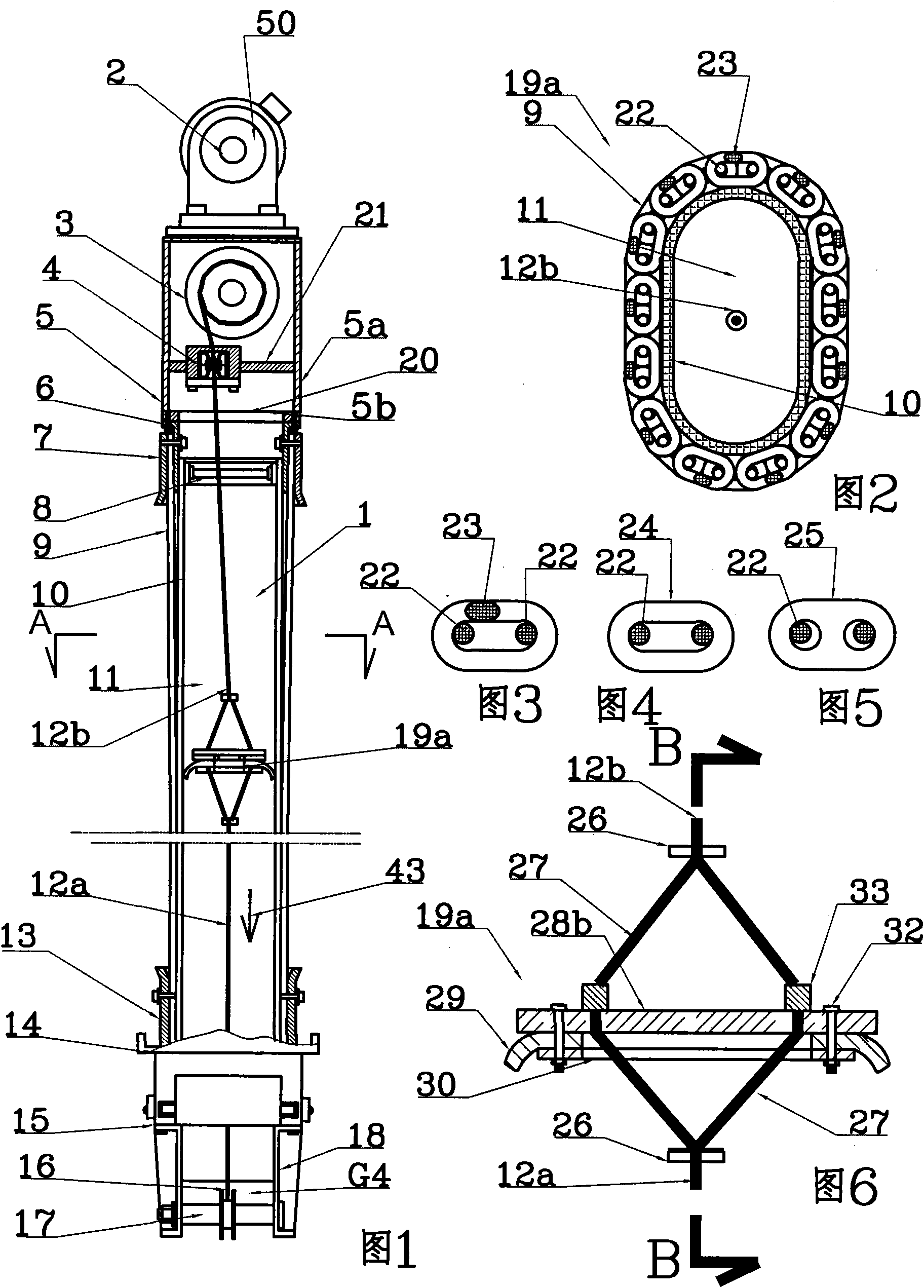
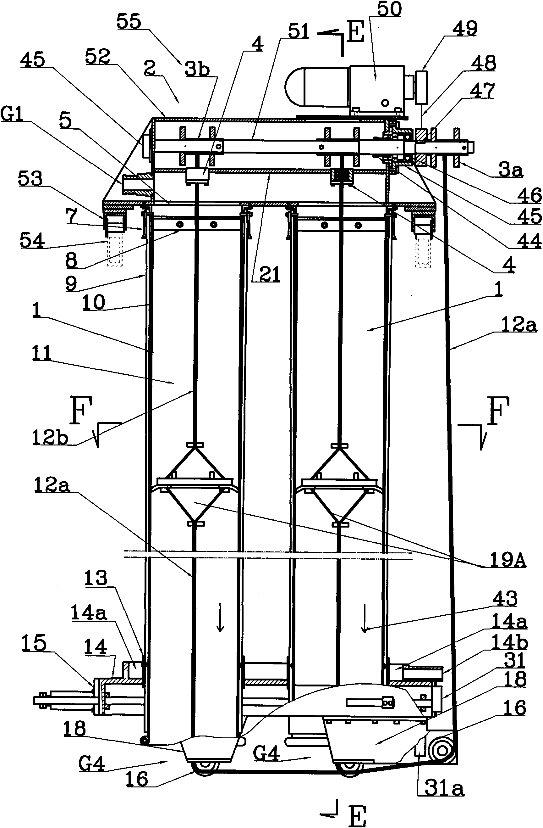
[0062] exist figure 1 , 2, 3, 6, 8, 9, 11, 17 and 18, shows the overall embodiment 1 of the apparatus of the present invention, the filter assembly in this embodiment comprises two A filter elements 55; two A filter elements 55 are arranged in parallel It is arranged on the two frame guide rails 54 of the frame 76 and can be relatively moved along the front and rear direction of the arrangement by the guide wheel assembly 53. The front and rear direction of the arrangement is also the direction of the pressing force of the pressing system; the A filter element 55 includes two filters Tube unit 1, upper flange 5, lower flange 14 and mechanical slag discharge assembly; all filter tube units 1 of A filter element 55 are arranged between upper flange 5 and lower flange 14; all filter elements of A filter element 55 The long axes of the filter pipe unit 1 are all in a central plane, which coincides with the long axis of the center of symmetry of the upper flange 5 and the lower f...

Embodiment 2

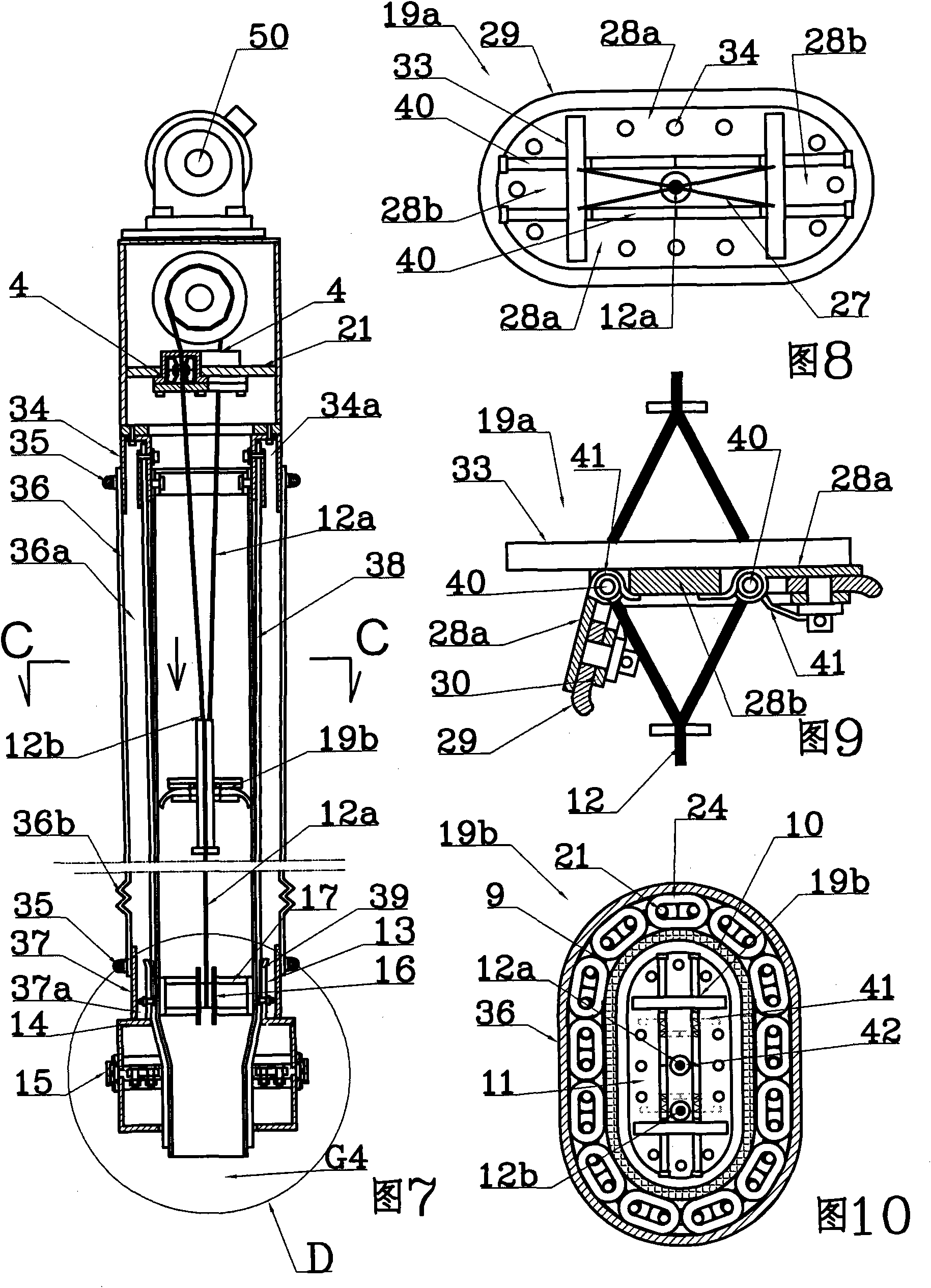
[0066] exist Figure 4 , 7 , 10, 12, 13, 14, 15, 16, 19 and 20, shows the overall embodiment 2 of the equipment of the present invention, the difference between this embodiment and embodiment 1 mainly lies in: the filter tube unit of B filter element 69 Tubular closed membrane 36 is set outside the outermost tubular filtrate of the outermost layer, and tubular closed membrane 36 has shrouded tubular filtrate 9 from the outside, forms annular filtrate collection chamber 36a between tubular closed membrane and tubular filtrate 9, tubular The upper end of the sealing film 36 is connected and sealed to the outer upper branch pipe 26 on the lower end surface of the upper flange 5 with a pipe hoop 35, and the lower end is connected to and sealed on the outer lower branch pipe 37 on the upper end surface of the lower flange 14, so that the horizontal filtrate collecting plate 14a Form the horizontal filtrate collection chamber 37a, the annular filtrate collection chamber 36a of each...


PUM


Abstract

The invention relates to a high-pressure compressing solid-liquid separation device of a flexible pipe. Pipe-shaped filtering medium at the utmost outside layer adopts a steel wire braid conveyer belt, and filter residue left on the filtering medium is removed in filtering by using a piston scrapper plate; the solid-liquid separation is accomplished in compressing by utilizing the principle of filter chamber variable-volume compression, the filter chamber is almost close to zero in volume after volume variation, and does not need a high-pressure pump to convey raw materials and does not need an additional compression water pump system or compression compressed air system as the filter pushing force of a filter press; and a pressing assembly of a pressing application system adopts an pressing reinforced connection rod mechanism, not only the pushing force is increased by dozens of times, but also the pressure is maximal when the pressing stroke is over with the filter pressure up to 2.5MPa. The device can adopt repeated treading and filtering, the alternating change of the thickness and the thinness of the raw materials in compression improves the filtering speed, washing speed and efficiency; the humidity of a filter cake is uniform; the washing regeneration of filter mediums is automatically accomplished; the residue discharge is automatically accomplished; the production process can realize complete automazation, so that the energy consumption is reduced, and the production efficiency is higher; and the manufacture cost is low due to the utilization of screw rod for clamping and compression.

Description

technical field [0001] The invention relates to a flexible tube high-pressure press solid-liquid separation device for solid-liquid treatment of viscous and fine-grained substances, especially suitable for papermaking wastewater treatment, sludge treatment, river dredging mud treatment, drilling mud treatment, and wet smelting wastewater treatment , Coal washing wastewater treatment, livestock and poultry breeding pollutants disposal and filling mining mud treatment and other projects of solid-liquid separation, also applicable to the requirements of pressing, leaching, hot press filtration or washing of chemical substances in industries such as traditional Chinese medicine, food and chemical industry; It is especially suitable for the production of liquid fuel from biological raw materials, activated sludge, coal and other raw materials; they all need to obtain filter residues with low liquid content under the premise of low energy consumption and high efficiency. Background...

Claims


Application Information

Patent Timeline
IPC IPC(8): B01D29/13B01D29/50B01D29/66
Inventor 张民良
Owner 张民良
Why Eureka
Try Eureka