Control system of ultrasonic welding machine

An ultrasonic welding and control system technology, which is applied in the field of welding devices and control systems of ultrasonic welding machines, can solve the problems of difficulty in grasping the direction of frequency adjustment, detection of frequency output status, and difficulty in realizing automatic control, etc., so as to achieve stable and reliable working performance , Eliminate temperature drift, and realize the effect of automatic fault diagnosis

Active Publication Date: 2009-11-11
浙江巨龙自动化设备股份有限公司
View PDF1 Cites 17 Cited by
  • Summary
  • Abstract
  • Description
  • Claims
  • Application Information

AI Technical Summary

Problems solved by technology

For example, for the self-excited oscillation mode, if the piezoelectric transducer has multiple resonance modes, this method is unreliable; for the phase-locked mode, the frequency automatic tracking needs to add a transducer compensation component in the drive circuit; and for the dynamic Feedback frequency tracking method, the direction of frequency adjustment is still difficult to grasp, and it is difficult to realize automatic control
In addition, in various frequency tracking methods, the feedback signals come from ultrasonic transducers or oscillation c

Method used


Image

  • Control system of ultrasonic welding machine

Examples


Embodiment Construction

[0024] The following are specific embodiments of the present invention and in conjunction with the accompanying drawings, the technical solutions of the present invention are further described, but the present invention is not limited to these embodiments.

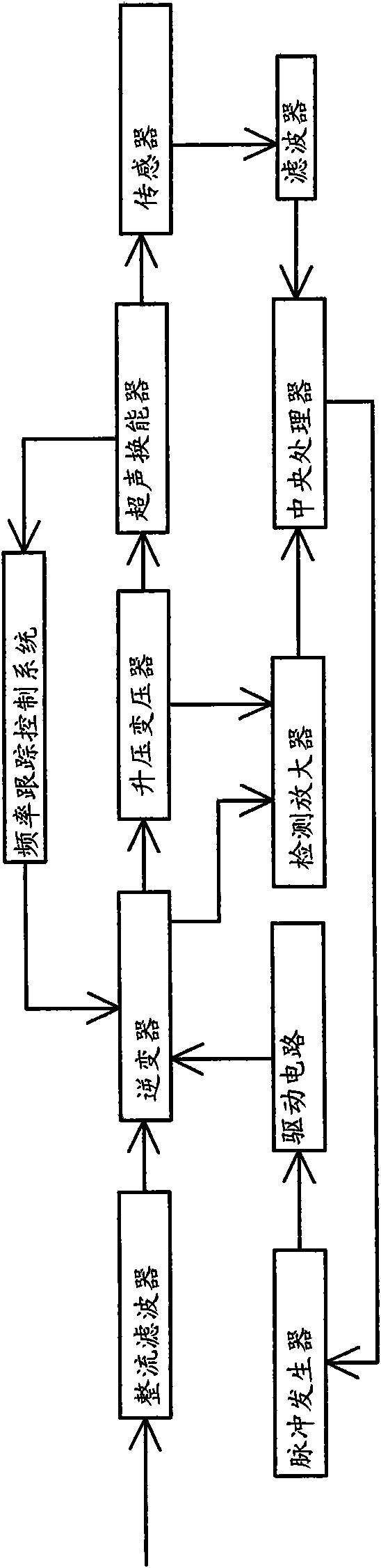
[0025] Such as figure 1As shown, the control system of this ultrasonic welding machine includes an inverter, an ultrasonic transducer and a central processing unit. A step-up transformer and a frequency tracking control system are connected between the inverter and the ultrasonic transducer. The inverter output The voltage is provided to the ultrasonic transducer after being boosted by the step-up transformer. The ultrasonic transducer can send a feedback signal to the inverter through the frequency tracking control system in real time. The ultrasonic transducer and the central processing unit are connected with a The sensor on the tool head is used to detect the output frequency of the tool head. A filter is connected bet...


PUM


Abstract

The invention belongs to the technical field of welding and relates to a control system of an ultrasonic welding machine. The control system solves the problems of poor working stability, low efficiency, low working quality and the like of the existing ultrasonic welding machine. The control system of the ultrasonic welding machine comprises an inverter, an ultrasonic transducer and a central processing unit; the inverter is respectively connected with the central processing unit and the ultrasonic transducer; a frequency tracking control system is connected between the inverter and the ultrasonic transducer; a sensor which is used for detecting a frequency signal and arranged at a tool head is connected between the ultrasonic transducer and the central processing unit; the inverter inputsvoltage and current signal parameters to the central processing unit, and the sensor inputs the frequency signal parameters at the tool head to the central processing unit, the processing is carriedout, and the controlled quantity is calculated; and a pulse generator which is used for generating a frequency pulse signal according to the controlled quantity is further connected between the inverter and the central processing unit. The control system of the ultrasonic welding machine has the advantages of simple structure, good stability, high working efficiency and quality and the like.

Description

technical field [0001] The invention belongs to the field of welding technology, and relates to a welding device, in particular to a control system of an ultrasonic welding machine. Background technique [0002] The ultrasonic power supply provides ultrasonic frequency alternating current signals to the ultrasonic transducer, and its realization circuit is also called the ultrasonic drive circuit. In the 20th century, with the rapid development of electronic technology, the power devices used in ultrasonic inverter power supply have gone through four stages: electron tube, thyristor, transistor and IGBT. In recent years, new circuit topologies and new power devices have been used in circuit design. The reliability, load adaptability, and product consistency of ultrasonic power supplies have been further improved. At the same time, the efficiency has also been greatly improved, and the volume of products has also been reduced at any time. [0003] The traditional ultrasonic ...

Claims


Application Information

Patent Timeline
IPC IPC(8): B23K20/10B29C65/08H02M7/42H02M1/14
Inventor 陈家乐
Owner 浙江巨龙自动化设备股份有限公司
Why Eureka
Try Eureka