Centrifugal force safety braking device of active track-locking type tramcar

A technology of safe braking and centrifugal force, which is applied in the field of mining vehicle components, can solve problems such as long braking response time, low reliability performance, and insensitive response, so as to avoid loss of life and property, high reliability performance, and fast braking response time short effect

Inactive Publication Date: 2009-11-18
吴强 +3
View PDF0 Cites 13 Cited by
  • Summary
  • Abstract
  • Description
  • Claims
  • Application Information

AI Technical Summary

Problems solved by technology

[0003] The purpose of the present invention is to solve the problems of insensitive response, long braking reaction time, easy to be ignored by people and low reliability

Method used


Image

  • Centrifugal force safety braking device of active track-locking type tramcar
  • Centrifugal force safety braking device of active track-locking type tramcar
  • Centrifugal force safety braking device of active track-locking type tramcar

Examples


specific Embodiment approach 1

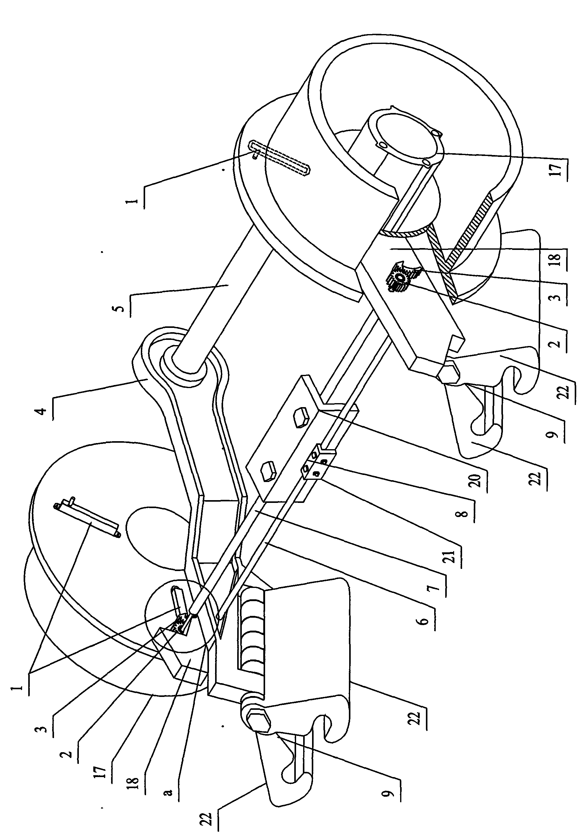
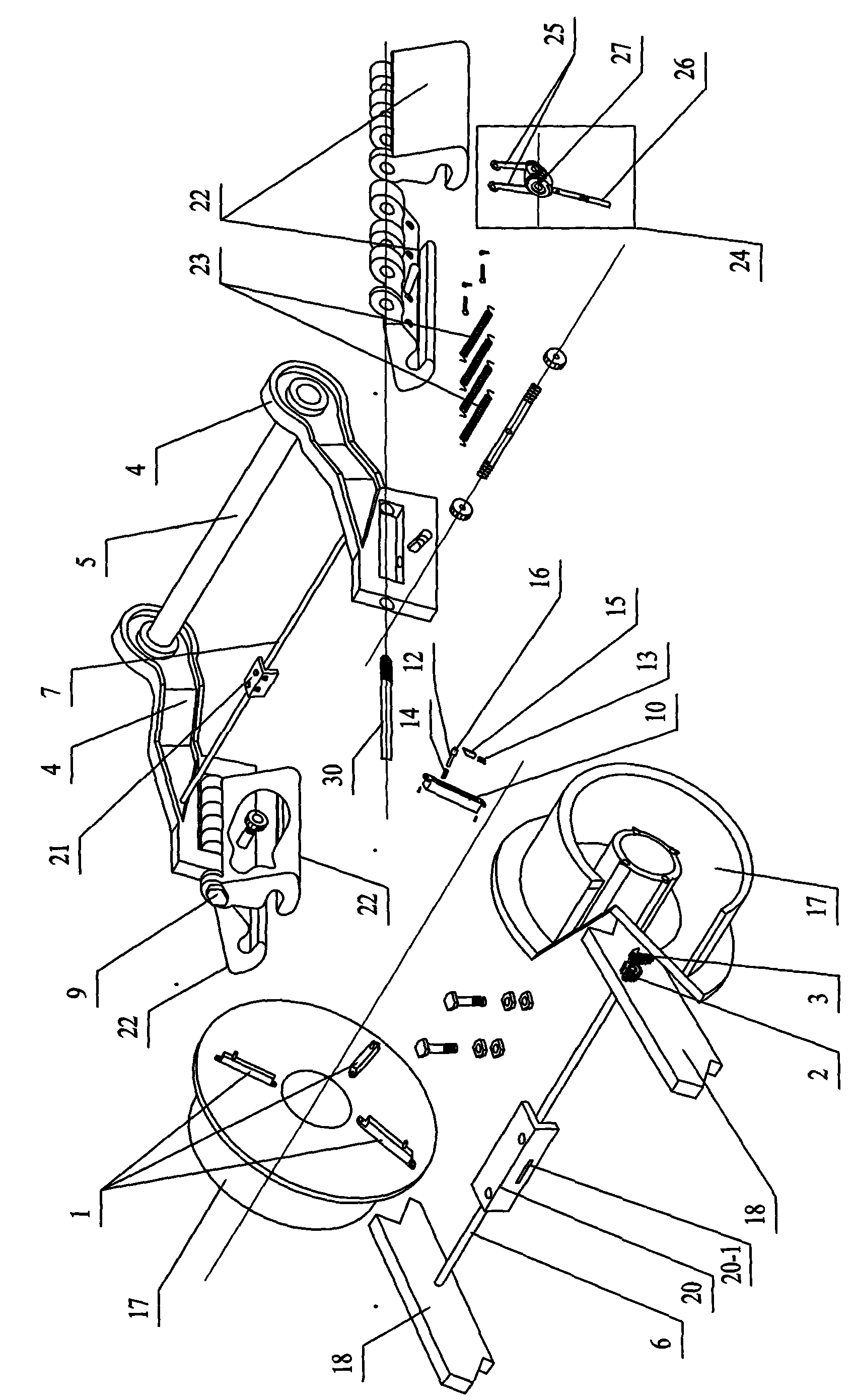
[0007] Specific implementation mode 1: Combination Figure 1~Figure 9 To illustrate this embodiment, the active rail-locking type mining car centrifugal force safety brake device of this embodiment consists of two sets of centrifugal force sensors, two gears 2, two racks 3, two main frames 4, a connecting shaft 5, and a fixed The connecting rod 6, the rotating connecting rod 7, the suspension switch 8, the two brake claws 9, the mine wheel body 17 and the mine cart frame 18, each group of centrifugal force sensors is composed of multiple centrifugal force sensors 1, The two sets of centrifugal force sensors are arranged on the two mine wheel bodies 17 opposite to each other. The multiple centrifugal force sensors 1 on each mine wheel body 17 are evenly arranged along the circumferential direction of the mine wheel body 17, and each centrifugal force The speed sensor 1 is arranged along the normal direction of the mine wheel body 17. Each centrifugal force sensor 1 consists of a sli...

specific Embodiment approach 2

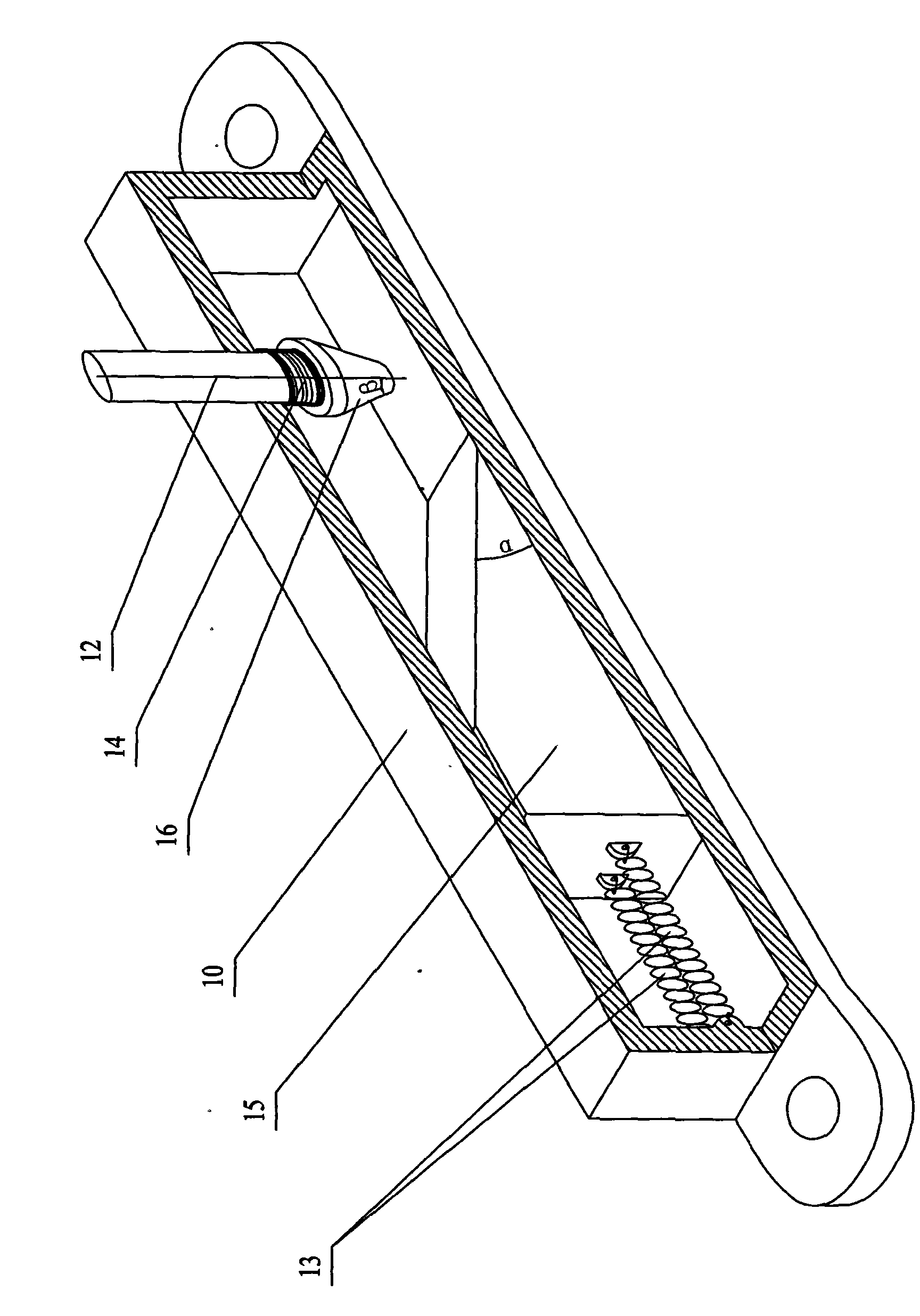
[0008] Specific implementation manner two: combination image 3 To describe the present embodiment, the sum of the wedge angle α of the wedge slider 15 and the taper angle β of the truncated cone body 16 of the present embodiment is less than 90°. With this arrangement, the contact area between the wedge-shaped slider 15 and the circular table body 16 is small, and the relative friction is small, so that the centrifugal force sensor is more sensitive and the braking time is shorter. The other composition and connection relationship are the same as in the first embodiment.

specific Embodiment approach 3

[0009] Specific implementation mode three: combination figure 1 with figure 2 To explain this embodiment, each group of centrifugal force sensors in this embodiment is composed of two to five centrifugal force sensors 1. With this setting, when a certain centrifugal force sensor fails and stops working, other centrifugal force sensors can act as a timely brake, so that the safety factor of the braking device is improved. Other components and connection relationships are the same as those in the first or second embodiment.


PUM


Abstract

The invention relates to a braking device of a tramcar, in particular to a centrifugal-type safety braking device of an active track-locking tramcar. The invention solves the problems that the existing passive anti-skid device is prone to insensitive response and long braking response time, the maintenance thereof is easily ignored, and the reliability thereof is low. In the invention, two groups of centrifugal speed sensors are arranged on two tramcar wheel bodies; the two ends of a rotary connecting rod are fixedly connected with two gears on the outer side of the tramcar frame by passing through the tramcar frame; two racks are mounted on the tramcar frame and engaged with the gears; one end of each rack, which is hook-shaped, is matched with the other end of a telescopic rod; two frameworks are arranged below the rotary connecting rod and connected with the tramcar frame via a suspender switch; two locking dogs are rotatablely mounted at the ends of the two frameworks, which are connected via a fixed connecting rod. The invention has the advantages of sensitive response, short braking response time, convenient maintenance and high reliability.

Description

Technical field [0001] The invention relates to a mine car brake device, belonging to the technical field of mine car parts. Background technique [0002] In order to ensure the safety of underground mine cart transportation, reliable braking of mine carts is one of the key technologies, and the braking device is to protect the safe production of mines. In the mining system and the inclined shaft engineering of small mines in other industries, in order to prevent the inclined shaft from racing cars, the past mainly adopted the setting of car stoppers at the wellhead and the setting of car doors at the bottom of the well, and some vehicles were installed in the shaft for safety. Rope, steel rope blocking car curtain, pneumatic safety door and front hook type, tail fork type, down swing type safety devices, or safety devices such as safety forks and safety hooks are installed on the mine cart. The reliability of the above braking devices is extremely low and the safety is not Can b...

Claims


Application Information

Patent Timeline
IPC IPC(8): B61H7/12
Inventor 吴强程巍张国华张保勇
Owner 吴强
Why Eureka
Try Eureka