
Rotary-type photocatalysed or adsorptive reactor

A wheel-type, photocatalytic technology, applied in the field of environmental protection, can solve the problems that affect the degradation of pollutants, COD reduction, catalyst, fluid and sunlight contact area are not large enough, etc., to improve the treatment effect, compact structure, and realize the effect of industrialization

Inactive Publication Date: 2009-11-18
NORTHEAST DIANLI UNIVERSITY +1
View PDF2 Cites 7 Cited by
  • Summary
  • Abstract
  • Description
  • Claims
  • Application Information

AI Technical Summary

Problems solved by technology

CN1868904 designed a drum-type photocatalytic reactor, all of which have achieved different degrees of effect, but the contact area of ​​catalyst, fluid and sunlight is still not large enough, which affects the degradation of pollutants and the reduction of COD

Method used


Image

  • Rotary-type photocatalysed or adsorptive reactor
  • Rotary-type photocatalysed or adsorptive reactor
  • Rotary-type photocatalysed or adsorptive reactor

Examples


Embodiment 1

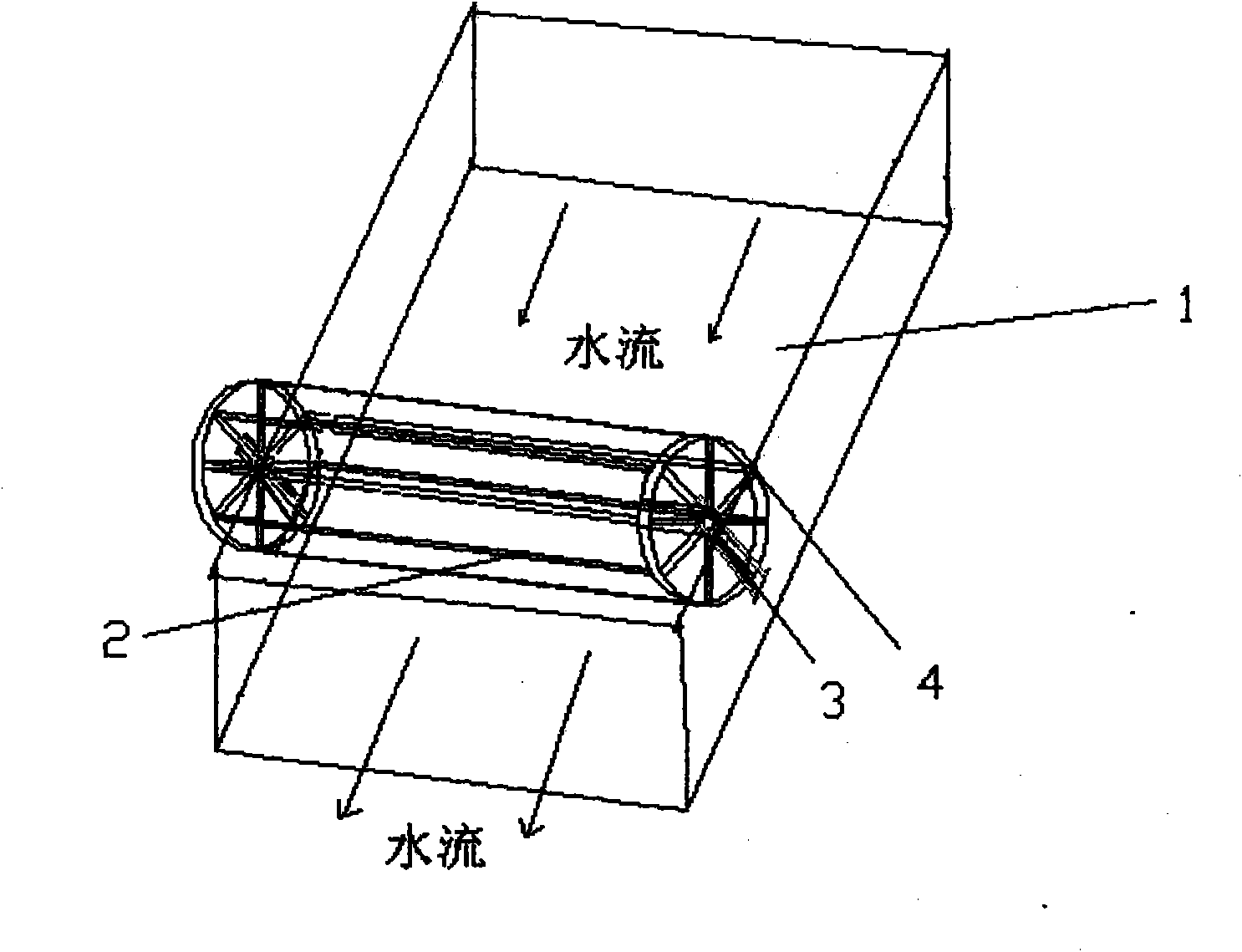
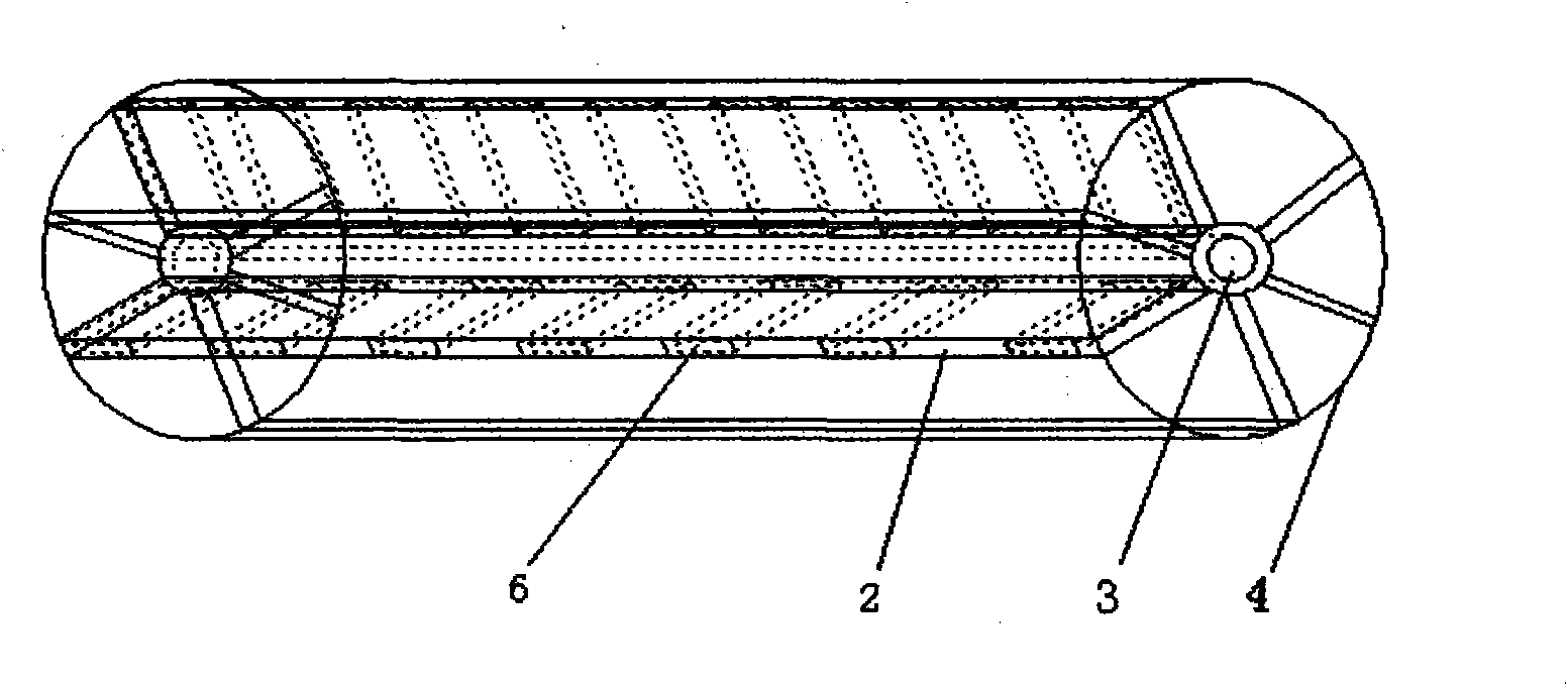
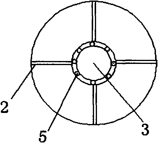
[0026] from figure 1 , figure 2 , image 3 , Figure 4 Visible, a kind of runner-type photocatalytic or adsorption reactor of the present invention mainly comprises tank 1, runner 4, water inlet and outlet, light source etc., is characterized in that: described tank 1 is placed obliquely, and runner 4 is horizontal Placed in the water tank 1, connected and fixed with the two sides of the water tank 1 through the central axis 3, the runner 4 is provided with a slot 2, and a thin plate 6 is inserted into the slot 2, and fixed by bolts. Both sides of the thin plate 6 are loaded with catalysts, films or adsorbents, 1 / 2 to 2 / 3 of the runner 4 is above the water surface, and the sunlight or ultraviolet lamp 9 is used as the light source; the water inlet is located on the top of the water tank 1, The water outlet is arranged at the bottom of the water tank, and the water flow impacts the thin plate 6, so that the runner 4 rotates slowly. If the water tank is installed indoors, i...

Embodiment 2

[0029] from Figure 4 , 5 , 6 Visible, a kind of runner type photocatalytic or adsorption reactor, mainly has water tank 1, runner 4, water inlet, water outlet, motor 7, light source 9, it is characterized in that: runner 4 is horizontally placed in water tank 1 , the central shaft 3 is connected to the bearings 5 ​​at the openings on both sides of the water tank 1, and the speed-regulating motor 7 is driven by the meshing of the gear on the central shaft 3 through the synchronous toothed belt 8; the runner 4 is provided with a card slot 2. There is a thin plate 6 built into the card slot 2, and both sides of the thin plate 6 are loaded with a catalyst thin layer, film or adsorbent. 1 / 2 to 2 / 3 of the runner 4 is above the water surface, and the sunlight or A UV lamp was used as the light source. Likewise, the sink is placed indoors with a UV lamp as the light source.

[0030] In the aforementioned rotary photocatalytic or adsorption reactor, the thin plate 6 is an ordinary ...


PUM


Abstract

The invention relates to a rotary-type photocatalysed or adsorptive reactor, comprising a sink, a rotating wheel, a water inlet and a water outlet and a light source. The reactor is characterized in that the sink is oblique; the rotating wheel is mounted on the sink horizontally, connected with two sides of the sink via a central axis and provided with a neck; a sheet is mounted on the neck, and both sides of the neck are loaded with catalyst, film or absorbing agent; parts of the rotating wheel breaks the surface of the water, and the sheet on the rotating wheel is shocked by stream to promote the rotating wheel to slowly rotate; sunlight or ultraviolet lamp can be taken as light source; or the rotating wheel can be connected with bearings on both sides of the sink via the central axis and connected with a reducing motor. The reactor can greatly increase the contact area among catalyst light sources and pollutants, enlarging photopermeability by using glass sheets, and prolonging reaction time. The reactor features simple and compact structure, little energy consumption, high clearance, low processing cost, moderate processing condition, and easy realization of industrialization.

Description

technical field [0001] The invention relates to the field of environmental protection, in particular to equipment used for degrading organic matter in urban micro-polluted water, or sewage produced in chemical industry, petroleum, petrochemical industry or medicine, in particular to a wheel-type photocatalytic or adsorption reactor. Background technique [0002] In terms of photocatalytic reactors studied at home and abroad, they can be divided into suspension type and supported type according to the form of catalyst in the reactor. The suspension type can improve the photocatalytic efficiency, but the recovery of the catalyst is difficult and the recovery cost is high. The supported type can solve the problem of catalyst recovery very well, but the specific area of ​​the reaction is greatly reduced, which reduces the photocatalytic efficiency. If the problem of the contact area of ​​the reaction in the reactor can be solved, the supported photocatalytic reactor will be a go...

Claims


Application Information

Patent Timeline
IPC IPC(8): C02F1/30C02F1/28
CPCY02W10/37
Inventor 孙旭辉程家庆王涛
Owner NORTHEAST DIANLI UNIVERSITY
Learn More