
Convective waste heat boiler for generating superheated steam

A technology of superheated steam and waste heat boiler, which is applied in the field of convection waste heat boiler, and achieves the effects of good thermal expansion resistance, improved conversion efficiency, and fewer welding seams

Inactive Publication Date: 2009-11-18
HARBIN INST OF TECH +1
View PDF1 Cites 10 Cited by
  • Summary
  • Abstract
  • Description
  • Claims
  • Application Information

AI Technical Summary

Problems solved by technology

[0003] The purpose of the present invention is to solve the problem that the existing convective waste heat boiler can only produce saturated steam and the steam temperature is 250°C, which is not suitable for directly feeding into the steam turbine for power generation, and provides a convective waste heat boiler that produces superheated steam

Method used


Image

  • Convective waste heat boiler for generating superheated steam
  • Convective waste heat boiler for generating superheated steam
  • Convective waste heat boiler for generating superheated steam

Examples


specific Embodiment approach 1

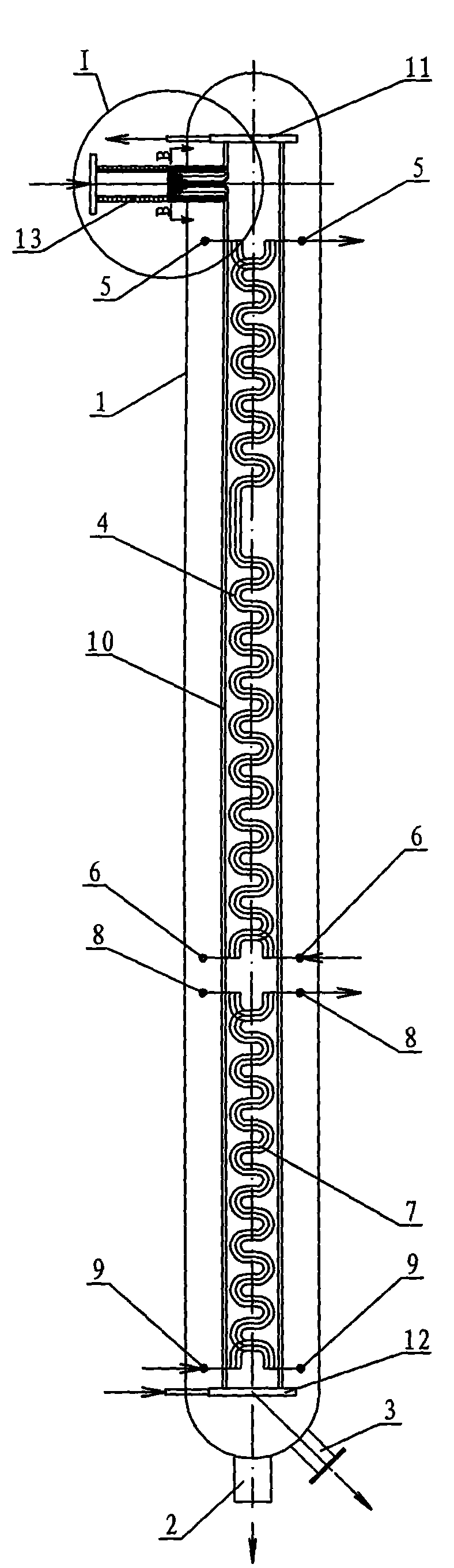
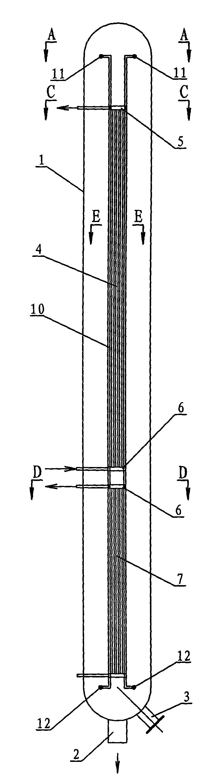
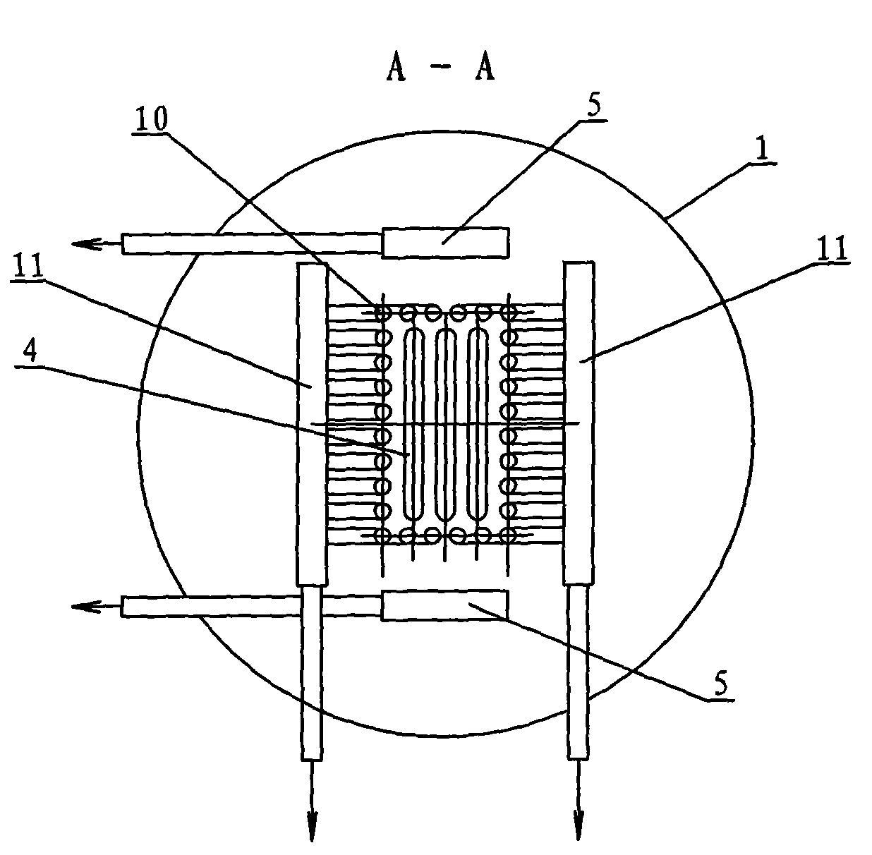
[0007] Specific implementation mode 1: Combination Figure 1~Figure 8 To explain this embodiment, this embodiment includes a boiler body 1, a pressure tube 2, at least two superheater coils 4, two superheater upper headers 5, two superheater lower headers 6, and at least one economizer Coiled tube bundle 7, two economizer upper header 8, two economizer lower header 9, tube assembly 10, two tube panel upper header 11, two tube panel lower header 12 and coarse The gas connecting pipe 13 and the pressure pipe 2 are arranged on the outer wall of the bottom of the boiler body 1 and communicate with the boiler body 1. The outer wall of the lower part of the boiler body 1 is provided with an inspection manhole 3, and the tube assembly 10 consists of several risers 10 -1. It is composed of several connecting plates 10-2 and several connecting pipes 10-3, several stand pipes 10-1 are arranged in parallel, and several stand pipes 10-1 are enclosed in a square tube shape, and two adjacent sta...

specific Embodiment approach 2

[0008] Embodiment 2: The working medium in the coiled tube bundle 4 of the superheater in this embodiment is superheated steam, the temperature of which is greater than the saturation temperature under the working pressure. Such a design can increase the superheating area of ​​the serpentine tube bundle 4 of the superheater and increase the temperature of the superheated steam outlet, thereby improving the power generation capacity. The other methods are the same as the first embodiment.

specific Embodiment approach 3

[0009] Embodiment 3: The working medium in the riser 10-1 and the connecting pipe 10-3 in the tube assembly 10 of this embodiment is water or a mixture of water and steam. This is designed to absorb the sensible heat of the crude gas in the cylindrical cavity of the tube assembly 10. The other methods are the same as the first embodiment.

[0010] The working process of the present invention: the crude gas enters the square cylindrical cavity of the tube assembly 10 through the crude gas connecting pipe 13, and the temperature of the crude gas at the inlet of the crude gas connecting pipe 13 is about 500-700°C. The inner cavity of the cylindrical tube assembly 10 flows downward, and the superheater serpentine tube on the superheater serpentine tube bundle 4, the economizer serpentine tube on the economizer serpentine tube bundle 7 and the tube assembly 10 The water in the riser 10-1 is heated to reach or close to the saturation temperature. At the same time, the water vapor in the...


PUM


Abstract

The invention relates to a convective waste heat boiler, in particular to a convective waste heat boiler for generating superheated steam. The invention solves the problem that the existing convective waste heat boiler can generate only 250-degree saturated steam which is not suitable for direct electricity generation. A plurality of standpipes are arranged in parallel to form a square-cylinder shape, a connecting board is arranged between two adjacent standpipes; tube components are arranged in a boiler body; two tube panel upper collecting headers, two tube panel lower collecting headers and the tube components form an independent water loop; two superheater upper collecting headers, two superheater collecting lower headers and at least two superheater S-shaped tube bundles form an independent water loop; two economizer upper collecting headers, two economizer lower collecting headers and at least one economizer S-shaped tube bundle form an independent water loop; a raw gas connecting tube is connected with the cylinder-shaped end surface on the outer side, which is surrounded by a plurality of connecting tubes of the tube components. By adopting the convective waste heat boiler, the invention is capable of generating superheated steam with the temperature is above 450 DEG C, which is suitable for electricity generation.

Description

Technical field [0001] The invention relates to a convection waste heat boiler. Background technique [0002] In the integrated gasification combined cycle (IGCC) system, the crude gas at the outlet of the coal gasifier generally has a relatively high temperature and therefore has a large amount of sensible heat energy. The amount of sensible heat is related to the type of gasifier. According to different coal gasification methods, the temperature of the synthetic gas at the outlet is generally about 1000 to 1500°C. Under current technical conditions, the reliable method of gas purification is still low-temperature wet purification. For this reason, the crude gas at the outlet of the coal gasifier must be cooled before purification, and recovery of the large amount of sensible heat energy contained in it is an important means to improve energy conversion efficiency. The sensible heat recovery system is very complicated, and it can be distributed in various forms in the entire pro...

Claims


Application Information

Patent Timeline
IPC IPC(8): F22B1/18F22G7/00
Inventor 邱朋华于龙杨龙滨张彦军谭建宇刘庆江吴少华姜丘陵王海刚李国继
Owner HARBIN INST OF TECH
Learn More