Antenna

An antenna and radio frequency feeder technology, applied in the directions of antennas, resonant antennas, slot antennas, etc., can solve the problems such as the inability to accommodate the bandwidth requirements of wireless mobile communication products of multiple standards at the same time, the large size of the antenna, etc. The effect of small, wide bandwidth

Active Publication Date: 2010-11-17
YUNNAN GALAXY STAR TECH LTD
View PDF7 Cites 0 Cited by
  • Summary
  • Abstract
  • Description
  • Claims
  • Application Information

AI Technical Summary

Problems solved by technology

[0005] The above two patents cannot accommodate the bandwidth requirements of multiple standard wireless mobile communication products at the same time, and the size of the antenna is relatively large compared to the installation space in the handheld device

Method used


Image

  • Antenna
  • Antenna
  • Antenna

Examples


Embodiment Construction

[0021] There are many combinations of embodiments of the antenna of the present invention, but the principle of forming the antenna method is consistent, and the embodiments of the present invention will be described in detail below in conjunction with the accompanying drawings:

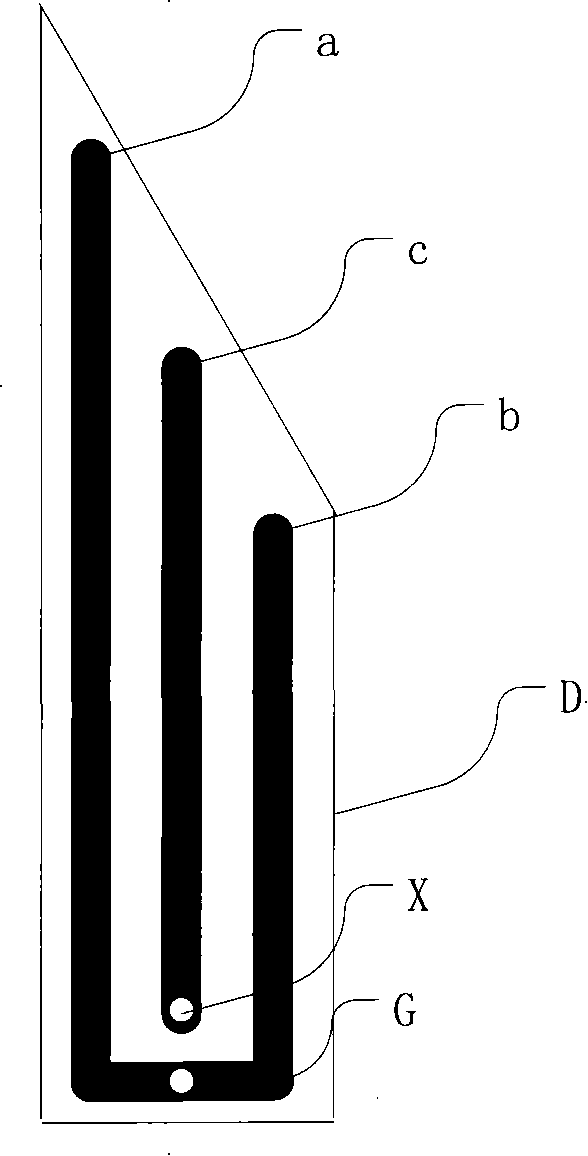
[0022] Refer to attached figure 1 , Embodiment 1 of the present invention is formed on the dielectric material (D) by combining the three conductors a, c, and b that do not intersect each other in the same plane. The a and b conductors are on both sides, and the c conductor is in the middle. The adjacent ends of the a and b conductors are electrically connected to each other, and then connected to the ground of the radio frequency signal to form a connection point (G). The c conductor is closest to the G point. One end of is connected to the signal terminal (X) of the radio frequency feeder, and the other end is suspended, wherein, the length of conductor a is greater than that of conductor b.

[00...


PUM


Abstract

The invention relates to an antenna which comprises three conductors a, b and c with certain lengths without intersection, wherein the conductor c is positioned between the conductor a and the conductor b; adjacent ends of the conductor a and the conductor b are electrically connected and then connected with a ground phase of a radio-frequency signal so as to form a connecting point (G); one end of the conductor c adjacent to the connecting point (G) is connected with a radio-frequency signal wire (X); and the length of the conductor a is larger than that of the conductor b so as to enhance the radiating capacity of an electromagnetic wave signal. To the best, the conductors a, b and c with certain lengths are manufactured on a dielectric material, and a comprehensive dielectric constant of the dielectric material between the conductor a and the conductor c is larger than or equal to a comprehensive dielectric constant of the dielectric material between the conductor b and the conductor c so as to increase the bandwidth. The conductors a, b and c are better to be circled on the dielectric material, wherein the length of the conductor a is larger than that of the conductor b, the length of the conductor a and the length of the conductor c are both larger than zero, and the length of the conductor b is larger than or equal to zero so as to reduce the volume.

Description

technical field [0001] The invention relates to a design method of a miniaturized ultra-wideband antenna. Background technique [0002] Antenna, as an indispensable key component of mobile communication products, its radiation efficiency, directivity, bandwidth, impedance matching characteristics, size and cost will have a great impact on mobile communication products. At the same time, the miniaturization, diversity, lightness, and aesthetic requirements of communication products are making antenna design a design art that takes into account miniaturization, bandwidth, radiation efficiency, and low cost. [0003] Chinese patent CN 1519986A discloses a "Microstrip Antenna with Increased Bandwidth", which uses a flat radiator and opens a gap at the input end of the radiator, so that the path length of the radio frequency signal on both sides of the radiator is different. achieve increased bandwidth. Its advantage is that it is easy to manufacture. [0004] Chinese patent C...

Claims


Application Information

Patent Timeline
Patent Type & Authority Patents(China)
IPC IPC(8): H01Q21/00H01Q21/24H01Q1/38H01Q9/04
CPCH01Q1/38H01Q9/27H01Q13/08H01Q13/10H01Q13/20H01Q13/206
Inventor 张一昉
Owner YUNNAN GALAXY STAR TECH LTD
Why Eureka
Try Eureka