Fluorescence observing device and fluorescence observing method

An observation device and fluorescence technology, which can be used in the fields of analysis using fluorescence emission, medical science, sensors, etc., can solve the problem of inconspicuous lesions

Inactive Publication Date: 2009-11-18
OLYMPUS CORP
View PDF1 Cites 36 Cited by
  • Summary
  • Abstract
  • Description
  • Claims
  • Application Information

AI Technical Summary

Problems solved by technology

[0004]However, since autofluorescent substances are originally contained in the biological tissue as the observation target part, by irradiating excitation light, not only the fluorescent pigment but also the autofluorescent substances are excited, which has the function of acquiring Defects that are not obvious in the lesion in the fluorescence image

Method used


Image

  • Fluorescence observing device and fluorescence observing method
  • Fluorescence observing device and fluorescence observing method
  • Fluorescence observing device and fluorescence observing method

Examples


Embodiment Construction

[0026] Regarding the fluorescence observation device 1 according to one embodiment of the present invention, refer to Figure 1 to Figure 7 for the following instructions.

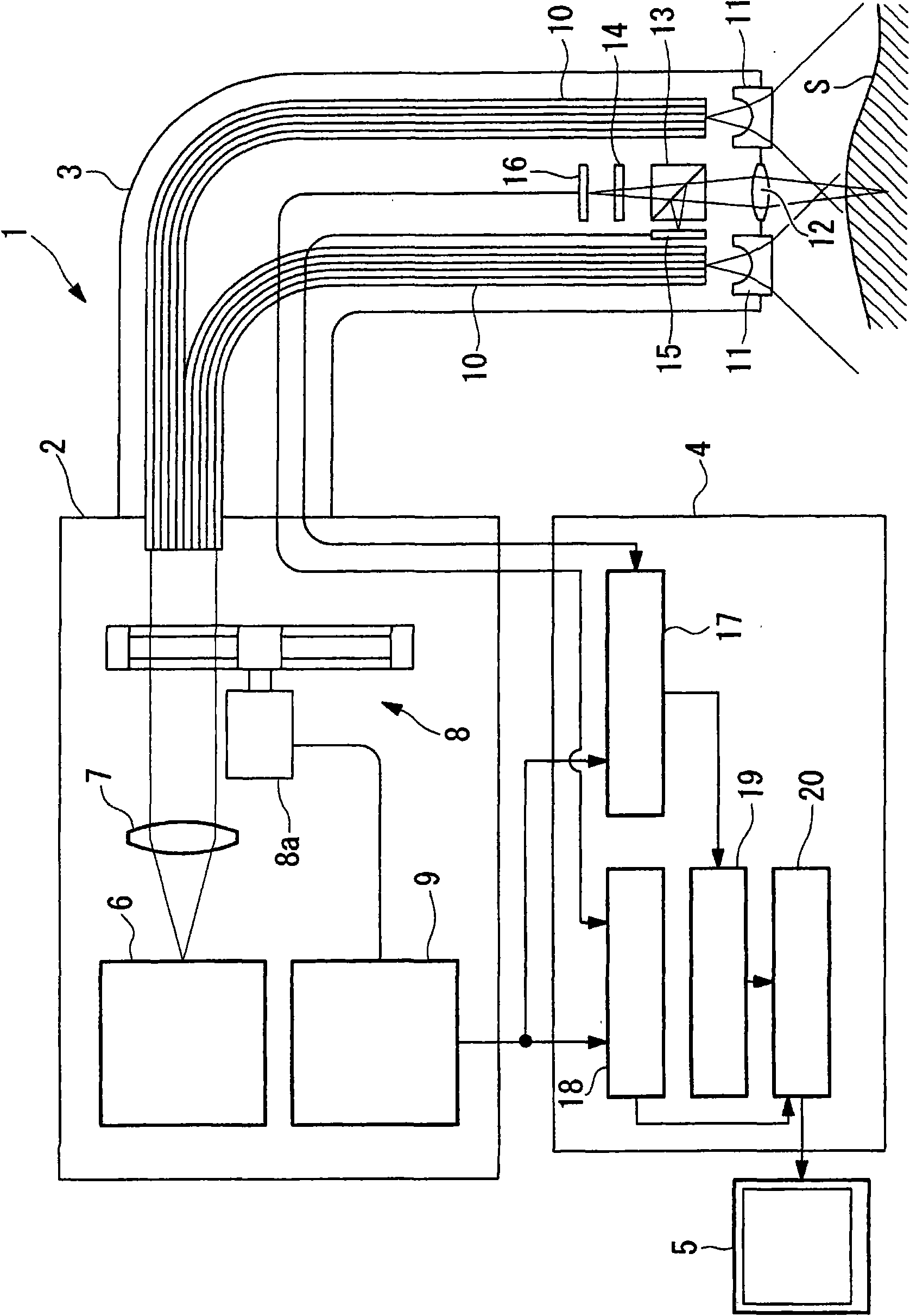
[0027] like figure 1 As shown, the fluorescence observation apparatus 1 of this embodiment has a light source unit 2 , an insertion unit 3 , an image processing unit 4 , and a monitor 5 .

[0028] The light source unit 2 has: a white light source 6 that generates white light; a collimator lens 7 that converts the white light from the white light source 6 into substantially parallel light; a rotary filter 8 that extracts light in a predetermined wavelength band from the white light; A filter control unit 9 that controls the filter 8 .

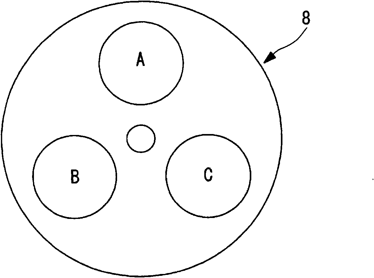
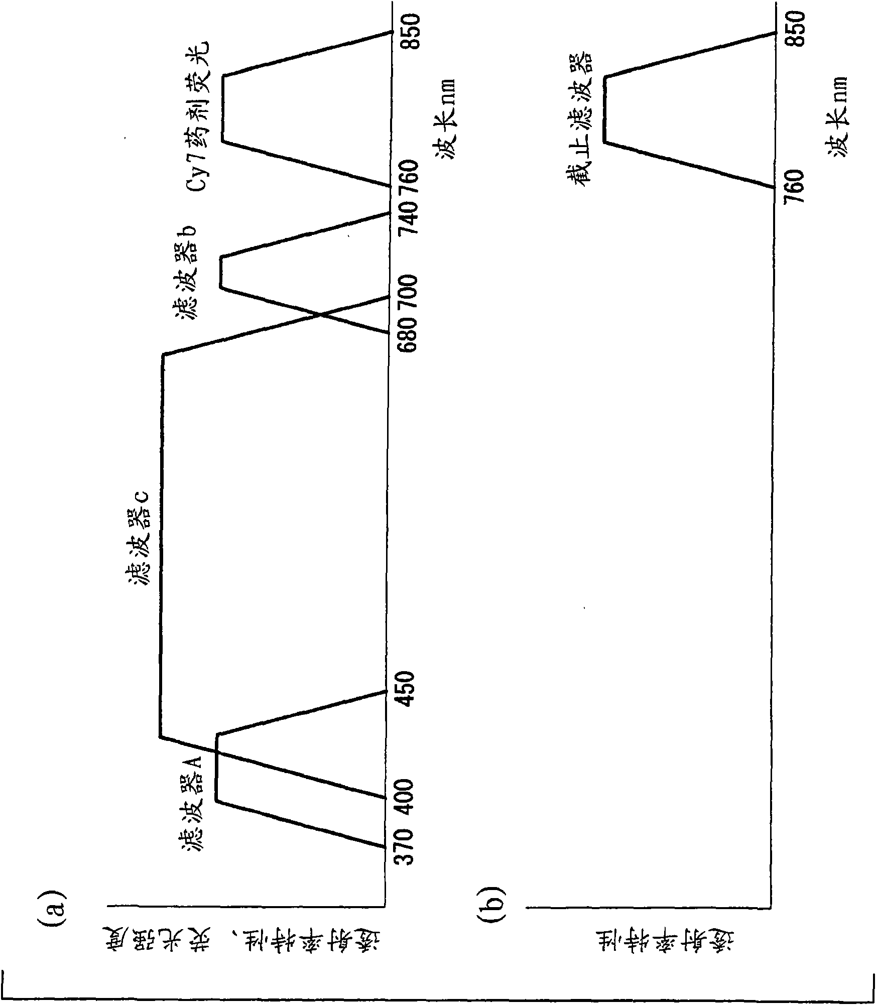
[0029] like figure 2 As shown, the rotary filter 8 has three different filters A, B, C. like image 3 As shown, these filters A, B, and C respectively have the following transmittance characteristics: filter A transmits light in the band of 370nm to 450nm, filter B tra...


PUM


Abstract

A lesion region in a captured fluorescent image can be made conspicuous, and an accurate diagnosis can be made. A fluorescence observing device (1) comprises a light source (2) for illuminating a region (S) to be observed with an illuminating light having a wavelength band absorbed by blood vessels and an exciting light for producing a drug fluorescence by exciting a fluorescent dye gathering singularly in a lesion, an imaging section (15, 16) for acquiring images by capturing reflected light and fluorescence produced when the region (S) is illuminated with the illuminating light and the exciting light, and an image processing section (4) for creating a reference image by smoothing the brightness of the reflected light image acquired by the imaging section (15, 16) and correcting the fluorescent image according to the acquired reference image.

Description

technical field [0001] The invention relates to a fluorescence observation device and a fluorescence observation method. Background technique [0002] Conventionally, there is known an endoscope system that irradiates an observation target site where a fluorochrome abnormally accumulated on a lesion such as a cancer cell is injected with excitation light that excites the fluorochrome to generate drug fluorescence, and By photographing the generated drug fluorescence, it is possible to obtain a fluorescence pattern with high brightness in the lesion (for example, refer to Patent Document 1). [0003] [Patent Document 1] Japanese Patent Laid-Open No. 8-224208 [0004] However, since the biological tissue to be observed originally contains autofluorescent substances, irradiating with excitation light not only excites the fluorescent pigment but also the autofluorescent substances, which has the disadvantage that the lesion is not conspicuous in the acquired fluorescence image....

Claims


Application Information

Patent Timeline
Patent Type & Authority Applications(China)
IPC IPC(8): A61B1/00
CPCA61B5/0071A61B1/043A61B5/489A61B1/0638A61B5/0084A61B1/0646A61B1/0655
Inventor 石原康成
Owner OLYMPUS CORP
Why Eureka
Try Eureka