
Laser soldering device

A technology of laser welding and laser beam, which is applied in the direction of laser welding equipment, welding equipment, welding equipment, etc., can solve the problems of reduced operating efficiency, excessive welding time, and inability to heat the rod-shaped terminal 5a

Active Publication Date: 2009-11-18
JAPAN UNIX
View PDF4 Cites 12 Cited by
  • Summary
  • Abstract
  • Description
  • Claims
  • Application Information

AI Technical Summary

Problems solved by technology

[0009] However, the ring-shaped laser beam can only heat the ring-shaped terminal 4a, but cannot heat the rod-shaped terminal 5a located in the middle of the ring-shaped terminal 4a.
Therefore, molten solder is rapidly cooled by the low-temperature rod-shaped terminal 5a, resulting in poor soldering. In this case, it takes a lot of soldering time, thereby reducing work efficiency.
In particular, in the case of continuous welding of multiple welding parts by welding robots, the overall work efficiency will be significantly reduced

Method used


Image

  • Laser soldering device
  • Laser soldering device
  • Laser soldering device

Examples


Embodiment Construction

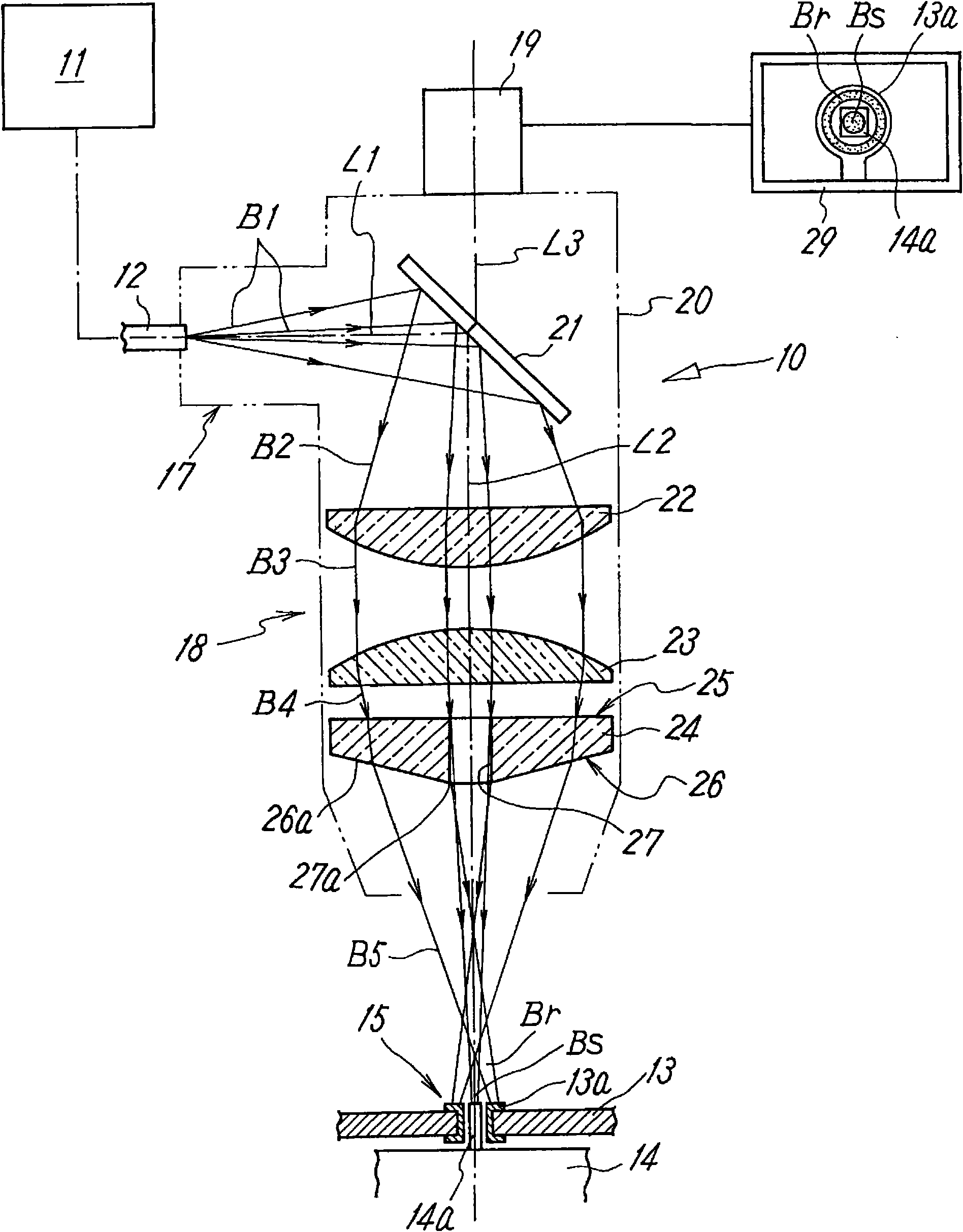
[0027] figure 1 It is a figure which schematically shows 1st Embodiment of the laser welding apparatus of this invention. In this figure, reference numeral "10" denotes a welder head provided on a multi-joint arm of a welding robot not shown; reference numeral "11" denotes a laser oscillator for outputting a laser beam B1; appended Reference numeral "12" denotes an optical fiber for guiding the laser beam B1 output from the laser oscillator 11 to the welder head 10. In addition, reference numeral “ 13 ” denotes a substrate provided with a printed circuit; and reference numeral “ 14 ” denotes electronic components soldered on this substrate 13 . Soldering is performed in a state where the rod-shaped terminal 14 a of the electronic component 14 is inserted into the ring-shaped terminal 13 a on the substrate 13 . Therefore, these ring-shaped terminal 13 a and rod-shaped terminal 14 a constitute a welding target 15 .

[0028] The welder head 10 has: an incident part 17, into w...


PUM


Abstract

A laser soldering device of a simple structure, which can, even in soldering between an annular terminal and a bar-like terminal inserted inside the annular terminal, efficiently solder them together by emitting a special-shaped laser beam capable of heating both the terminals without causing burning of electronic components. In the laser soldering device for performing soldering by applying a laser beam to objects to be soldered, some of optical lenses are cone lenses. The incident and exit surfaces of each cone lens have a circular conical shape, and the cone lens has at the center has a center hole having a smaller diameter than the circular laser beam entering the cone lens. The circular laser beam is converted by the cone lenses into a double circular beam having an annular ring section and a spot section located at the center of the ring section. The converted laser beam is applied to objects to be soldered.

Description

technical field [0001] The present invention relates to a laser welding device for precisely welding electronic components such as ICs and LSIs or other workpieces with laser beams. Background technique [0002] The technique of welding by laser is an existing known technique, as disclosed in Patent Document 1 and Patent Document 2 below. These techniques are welding techniques in which a laser beam is irradiated from a welding machine head of a welding device to a welding object such as a printed circuit board, and the heat of the laser beam melts the solder, and has the advantage of soldering without touching the solder. [0003] However, there are following problems in the prior art, such as Figure 7 with Figure 8 As shown, since the circular laser beam 2 is irradiated from the welder head 1 to the welding object 3 in a point-like manner, and the welding wire 8 supplied from the nozzle 7 is melted by the laser beam 2, welding is performed. Therefore, When the welding ...

Claims


Application Information

Patent Timeline
Patent Type & Authority Applications(China)
IPC IPC(8): B23K1/005B23K1/00B23K26/03B23K26/06B23K26/073H05K3/34B23K101/42
CPCB23K26/0648B23K26/0652
Inventor 河野宽史
Owner JAPAN UNIX
Features
  • Generate Ideas
  • Intellectual Property
  • Life Sciences
  • Materials
  • Tech Scout
  • Unparalleled Data Quality
  • Higher Quality Content
  • 60% Fewer Hallucinations
Learn More