Fuel or gas molten salt furnace

A molten salt furnace and gas technology, applied in the field of oil-fired gas molten salt furnace, can solve the problem that ordinary heating facilities cannot provide high temperature above 300 ℃, and achieve the effect of improving combustion efficiency

Inactive Publication Date: 2009-11-25
常州能源设备总厂有限公司
View PDF0 Cites 12 Cited by
  • Summary
  • Abstract
  • Description
  • Claims
  • Application Information

AI Technical Summary

Problems solved by technology

The invention solves the disadvantage that ordinary heating facilities cannot provide high temperature above 300°C, and by using the heating furnace of the invention, fuel oil or natural gas can be fully bu

Method used


Image

  • Fuel or gas molten salt furnace

Examples


Embodiment Construction

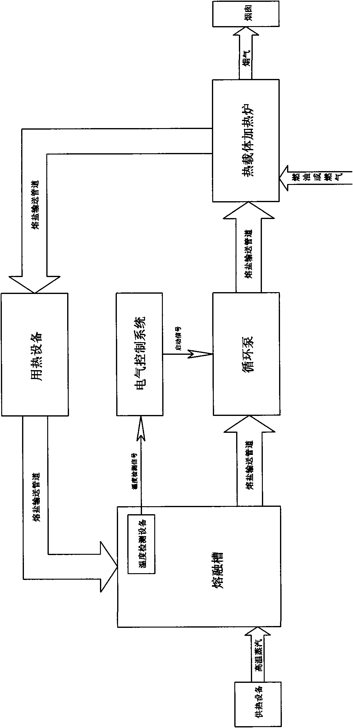
[0007] The working process of the present invention is as follows: the mixed inorganic salt powder particles are added into the melting tank, and under the heating of the high-temperature steam introduced in the melting tank, the temperature in the melting tank reaches 142°C, and the mixed inorganic salt powder particles Melted into liquid, the temperature detection device installed in the melting tank detects that the temperature reaches the melting temperature of the inorganic salt, and returns an electrical signal to the electrical control system. After receiving the electrical signal, the electrical control system sends a signal to start the circulation pump. signal, the circulating pump starts to work, and the power generated during the working process of the circulating pump presses the mixed inorganic salt in the melting state into the delivery pipeline, and transports it to the heat carrier heating furnace to continue heating. The heating furnace of the present invention...


PUM

PropertyMeasurementUnit
Melting pointaaaaaaaaaa

Abstract

The invention relates to a fuel or gas molten salt furnace which comprises five parts i.e. a smelt tank, a circulating pump, a heat carrier heating furnace, an electric control system and a transportation pipeline. The fuel or gas molten salt furnace is a direct current type heating furnace which takes fuel or gas as fuels, takes molten salts as a heat carrier, forces liquid phase to circulate by utilizing power generated by the circulating pump to transport heat energy to heat consuming equipment, and then returns he heat energy to the smelt tank to carry out circulation heating.

Description

technical field [0001] The invention belongs to a heating facility, in particular to a fuel gas molten salt furnace. Background technique [0002] The heat transfer medium currently used is mainly steam and heat transfer oil. In view of the temperature required by heat-using equipment, it is difficult for heating facilities using steam and heat transfer oil as a medium to reach a high temperature of more than 300 ° C, and ordinary heat carrier heating furnaces Using solid fuel (mainly coal and wood waste), using this fuel for heating, not only has low heating efficiency, but also causes a lot of environmental pollution. Contents of the invention [0003] The object of the present invention is to provide a once-through heating furnace that uses fuel oil or natural gas as fuel, molten salt as heat carrier, and uses circulation pump to force liquid phase circulation to transfer heat energy to heat-consuming equipment and then return to reheat. The invention solves the disadv...

Claims


Application Information

Patent Timeline
IPC IPC(8): F24D7/00
Inventor 王云祥丁宏
Owner 常州能源设备总厂有限公司
Why Eureka
Try Eureka