Monopulse radar system based on time modulation antenna array

A single-pulse radar, time modulation technology, applied in radio wave measurement systems, radio wave reflection/re-radiation, utilization of re-radiation, etc., can solve the problem of increasing the acquisition angle error signal time and other issues

Inactive Publication Date: 2009-11-25
UNIV OF ELECTRONIC SCI & TECH OF CHINA
View PDF0 Cites 46 Cited by
  • Summary
  • Abstract
  • Description
  • Claims
  • Application Information

AI Technical Summary

Problems solved by technology

From the perspective of angle measurement error analysis, there is only one error signal for a target echo signal. In order to improve the tracking distance and measurement accuracy, or to pr

Method used


Image

  • Monopulse radar system based on time modulation antenna array
  • Monopulse radar system based on time modulation antenna array
  • Monopulse radar system based on time modulation antenna array

Examples


Embodiment 1

[0101] Example 1: Phased array monopulse radar device based on time-modulated antenna array (high-order sideband suppression)

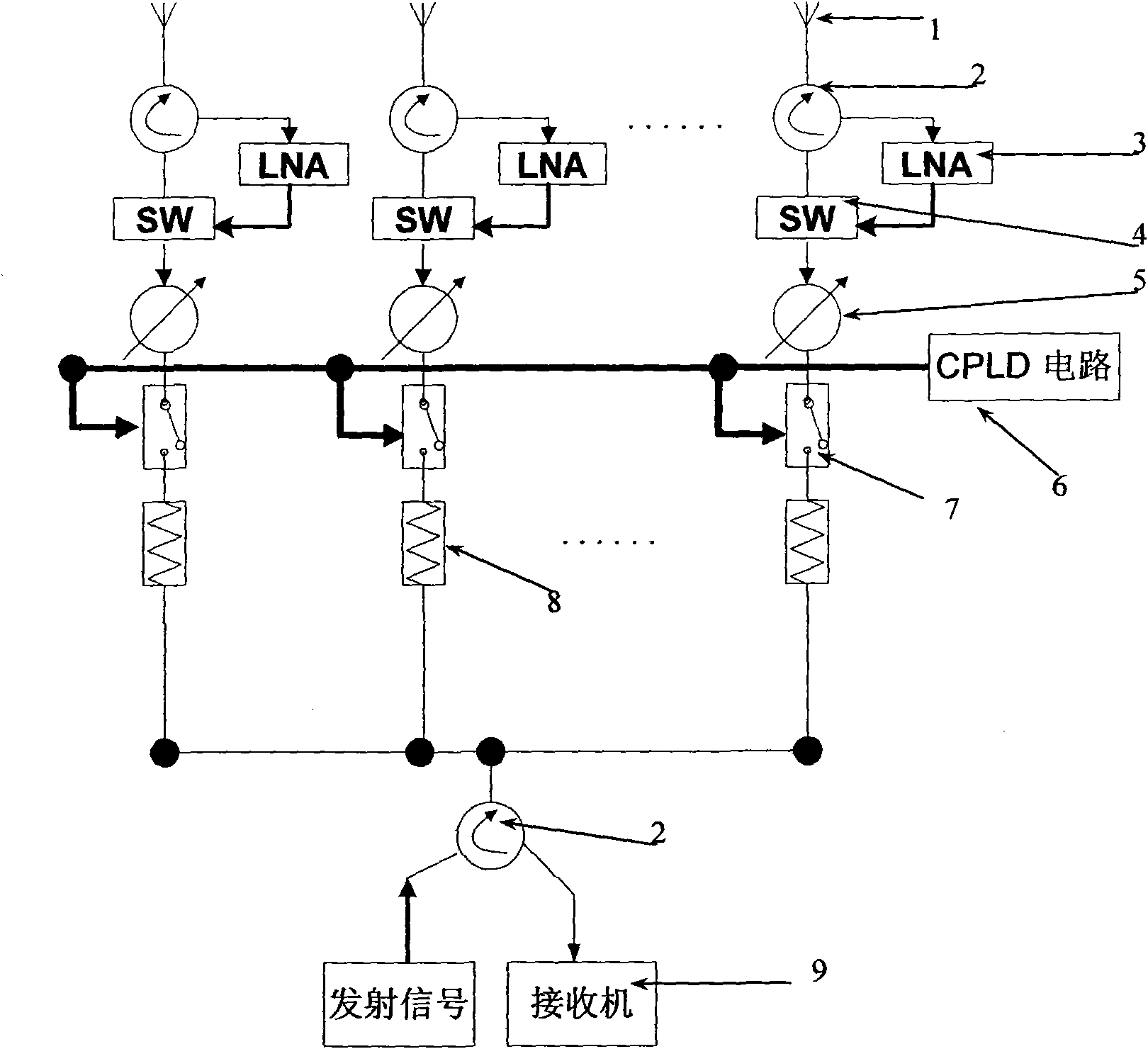
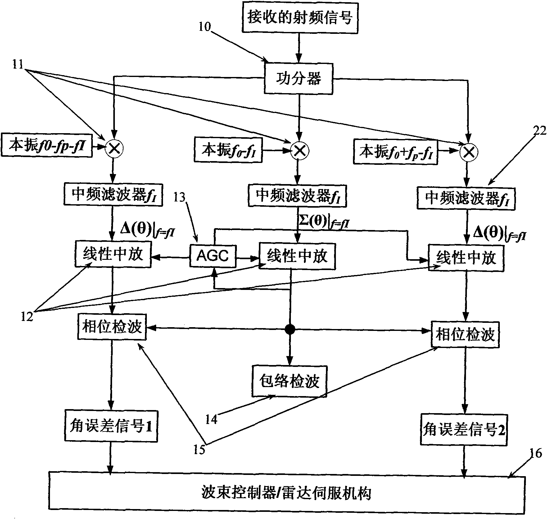
[0102] Refer to figure 1 with Figure 6 In this embodiment, a time modulation array composed of N=16-element omnidirectional array units is adopted, and the number of array elements opened in each time step is M=8. In order to obtain a good performance receiving sum and difference beam, that is, a higher gain sum and difference beam, a lower difference beam zero depth, and a larger difference beam zero slope, the differential evolution algorithm (Differential Evolution Strategy) is used in this embodiment. The design variables are determined, and the static excitation amplitude of the time modulation array and the spatial position of the unit are used as design variables in this embodiment to optimize the performance of the receiving and difference beam. In addition, sideband radiation higher than the first sideband that is not beneficial to the system w...

Embodiment 2

[0105] Embodiment 2: Phased array monopulse radar device based on time-modulated antenna array (no high-order sideband suppression)

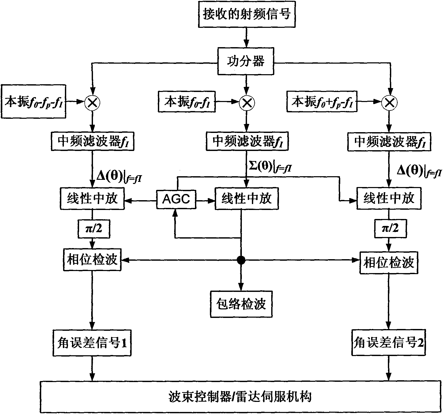
[0106] Refer to figure 1 with Figure 6 In this embodiment, a time modulation array composed of N=16-element omnidirectional array units is still used, and the number of array elements opened in each time step is M=8. In order to obtain a good receiving sum and difference beam, that is, a higher gain sum and difference beam, a lower difference beam zero depth, and a larger difference beam zero slope, the differential evolution algorithm is used in this embodiment to determine the design variables. The static excitation amplitude of the time modulation array and the spatial position of the unit are used as design variables in this embodiment to optimize the performance of the receiving and difference beam. In addition, in this embodiment, sideband radiation higher than the first sideband that is not beneficial to the system is not suppressed as one ...


PUM


Abstract

The invention discloses a phased array monopulse radar system based on the time modulation antenna array technology. The basic scheme of the invention comprises an antenna array comprising a plurality of array antenna units, a high-speed radio frequency switch controlled by a complex programmable logic device, a radar receiver, and the like; based on the basic scheme, a power-divider, a mixer, and an intermediate frequency amplifier are reasonably added in the radar receiver, and an amplitude detector, a phase detector and the like are reasonably added at a data processing terminal to form various improved schemes of the invention. With the invention, sum beams and difference beams are easily generated simultaneously, therefore, the transmission of simultaneous frequency diversity signals can be easily realized, and difference beams of higher performance (beam gain, null depth, slope of zero, and the like) can be easily obtained. The invention can be widely used in the phased array monopulse radar systems having application background adding radar reconnaissance difficulty of enemy, or used in radar systems of other target angle measurement and precision angle tracking.

Description

Technical field [0001] The invention belongs to the technical field of radar engineering, and particularly relates to a phased array monopulse radar system based on a time-modulated antenna array. Background technique [0002] The concept of the monopulse antenna originated from the interferometer. In theory, the monopulse angle measurement method only needs one echo pulse to obtain all the angle error information of the target, so the time required to obtain the angle error information is very short. The single pulse method has a high accuracy of angle measurement, so it is mostly used in precision tracking radar systems. There is no other tracking system that can exceed the single pulse tracking accuracy. [0003] The precision tracking system currently used is mainly a monopulse tracking system. The angular tracking accuracy of the American missile range measurement radar is as high as 0.1 digits, which is the most accurate ground tracking system known so far. The KSA (Ka-band...

Claims


Application Information

Patent Timeline
IPC IPC(8): G01S13/68G01S7/02
Inventor 杨仕文陈益凯李钢聂在平
Owner UNIV OF ELECTRONIC SCI & TECH OF CHINA
Why Eureka
Try Eureka