
Method for forming and capturing liquid drops based on three-layer sandwich disc-type chip and application thereof

A disc-type, chip-based technology, applied in chemical instruments and methods, laboratory containers, dissolution, etc., can solve the problems of droplet size change, uncapturable, and droplet cannot enter the capture area, etc., to achieve capture efficiency High, avoid the effect of use

Inactive Publication Date: 2009-12-02
DALIAN INST OF CHEM PHYSICS CHINESE ACAD OF SCI
View PDF0 Cites 24 Cited by
  • Summary
  • Abstract
  • Description
  • Claims
  • Application Information

AI Technical Summary

Problems solved by technology

This feature determines that the size of the droplet must be precisely controlled to match the capture area. If it is too large, the droplet cannot enter the capture area, and if it is too small, it will not be captured.
In addition, small fluctuations in fluid flow rate can cause changes in droplet size, resulting in inefficient capture of droplets.

Method used


Image

  • Method for forming and capturing liquid drops based on three-layer sandwich disc-type chip and application thereof
  • Method for forming and capturing liquid drops based on three-layer sandwich disc-type chip and application thereof
  • Method for forming and capturing liquid drops based on three-layer sandwich disc-type chip and application thereof

Examples


Embodiment 1

[0040] Example 1 In Situ Formation and Capture of Arrayed Droplets

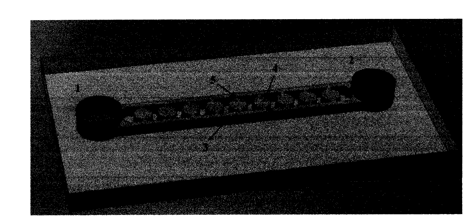
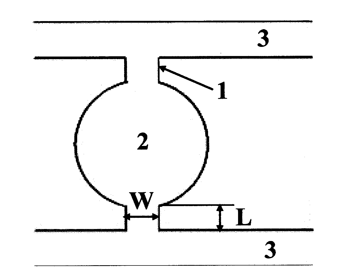
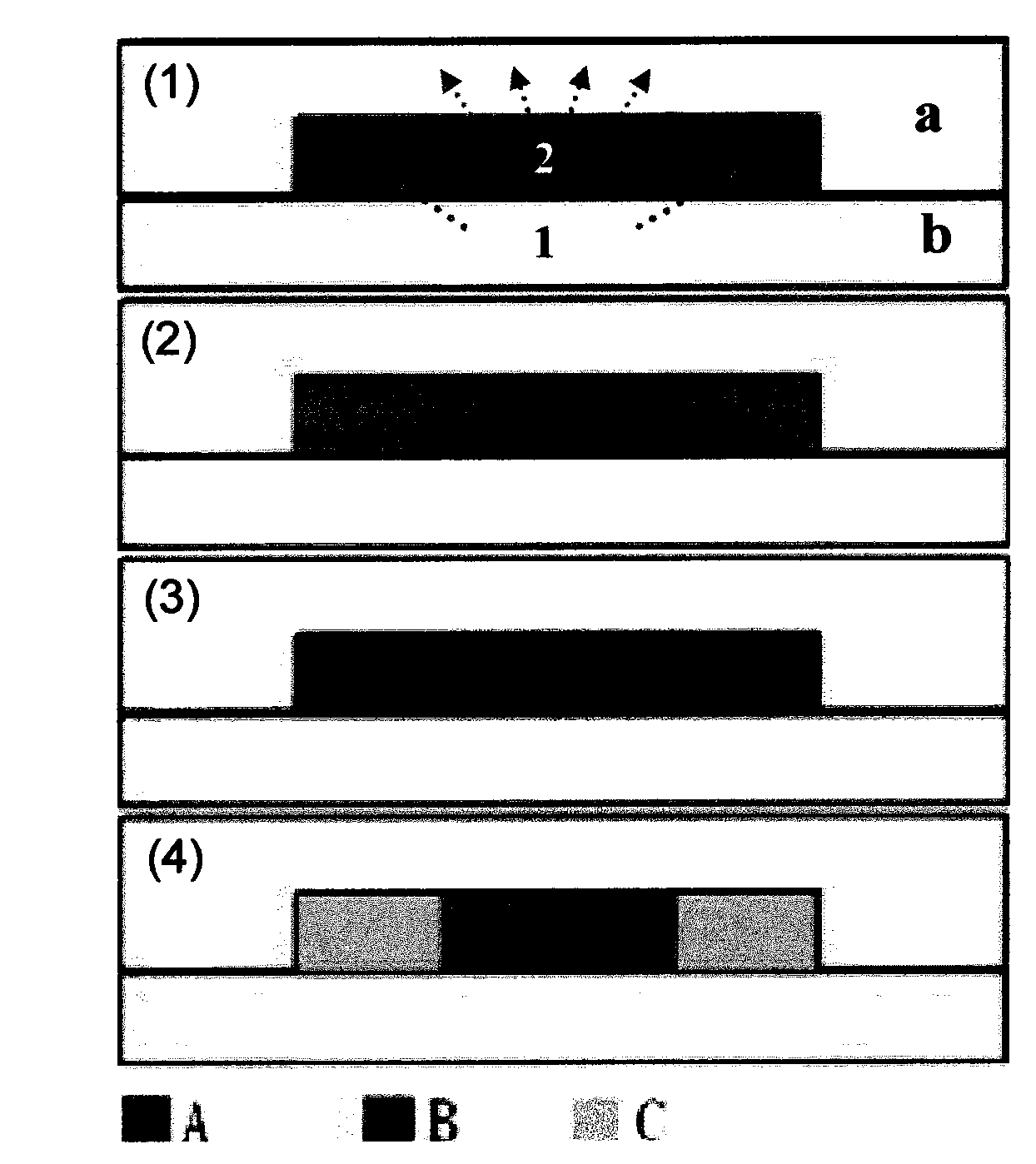
[0041] Will figure 1 Put the PDMS chip shown in a vacuum desiccator and degas it in vacuum for 3-5 minutes. After taking it out, add methylene blue aqueous solution in reservoir 1, and pump it with a vacuum pump in reservoir 2. The methylene blue aqueous solution fills the main channel and forms a trap. area of ​​air bubbles (see Figure 3-1 , 4-1), due to the gas permeability of PDMS, the air in the capture area slowly enters the PDMS body, and the methylene blue solution in the main channel gradually fills the capture area (see Figure 3-2 , Figure 4-2 ), after the subunit blue solution is completely filled with the capture area, the subunit blue solution in the main channel is evacuated in the reservoir 2, and the subunit blue solution in the capture area forms water droplets (see Figure 3-3 , Figure 4-3 ), and then add mineral oil to the reservoir 1, the mineral oil fills the main channel under cap...

Embodiment 2

[0042] Example 2 Formation of pH Gradients in Array Droplets

[0043] Will Figure 8 Put the three-layer sandwich disc chip shown in a vacuum desiccator and degas it for 3-5 minutes. After taking it out, add pH indicator solution to the liquid storage tank near the center of the circle, and use a vacuum pump to pump the liquid storage tank away from the center of the circle. After a while, the pH indicator solution enters the main channel, and wait until the pH indicator solution fills the capture area, then centrifuge the chip for 55 seconds (2500 rpm), and then add Fc40 (fluorinated oil) to the reservoir near the center of the circle respectively, Formation of Fc40-coated pH indicator droplets. Ammonia gas is continuously fed into the lower channel, and the ammonia gas diffused across the membrane reacts with the pH indicator solution, resulting in a change in the color of the pH indicator solution (see Figure 9 ). Due to the absorption of ammonia gas by the pH indicator...

Embodiment 3

[0044] Example 3 Coordination reaction of various metal ions and ammonia gas in the array droplet

[0045] use Figure 8 The chip shown and the method described in embodiment 2 form NiCl respectively 2 / Fc40, CuSO 4 / Fc40 and Fe(NO 3 ) 3 / Fc40 array droplets, ammonia gas is continuously fed into the lower channel, the ammonia gas diffused across the membrane is absorbed by the metal salt solution, and reacts with metal ions, the amount of ammonia gas absorbed by each droplet is different, resulting in the formation of metal ions -Crystals of ammonia gas complexes (see Figure 10-3 , 10-4), solution, precipitation and other different forms (see Figure 10 , 11, 12).


PUM


Abstract

The invention relates to a method for forming and capturing liquid drops based on a three-layer sandwich disc-type chip and application thereof, wherein the chip with a geometric micro-structure and consisting of a main channel, a side channel and a capturing area is designed and uses the difference of the surface tension in the channels with different widths to induce the in-situ formation and capture of the liquid drops. The method has the following advantages that: the in-situ formation and capture of the liquid drops is achieved by using a simple structure; the formation of the liquid drops does not need a surfactant to prevent the surfactant from influencing the reactions in the liquid drops; the formation of the liquid drops is not influenced by channel surface properties so that oil-in-water liquid drops can be achieved on an unmodified PDMS chip; the formation of the liquid drops does not need precise control of the fluid flow rate, and the flowage of the fluid adopts a liquid storage tank vacuumizing mode to avoid using a precise injection pump and reduce the experimental cost; and the captured liquid drops are used as array micro-reactors to achieve the chemical reactions of gas-liquid two phases in the liquid drops for the first time.

Description

technical field [0001] The invention relates to microfluidic chip technology, and in particular provides a method for forming and capturing droplets based on a three-layer sandwich disk chip and its application. Background technique [0002] Microfluidic chip is an emerging science and technology platform. It relies on a chip of a few square centimeters, which forms a network of microchannels and runs through the entire system with controllable fluids. It can replace various functions of conventional chemical or biological laboratories. Its basic features are extremely low sample consumption, fast sample processing speed, and multiple unit technologies including reaction and detection can be flexibly combined and scale-integrated on a tiny platform. So far, microfluidic chips have covered more and more fields, and new branches have been derived continuously. [0003] Recently, a droplet technology has been developed on microfluidic chips. The basic point of this technology ...

Claims


Application Information

Patent Timeline
IPC IPC(8): B01J19/00B01L3/00B01F5/00
Inventor 秦建华张清泉林炳承
Owner DALIAN INST OF CHEM PHYSICS CHINESE ACAD OF SCI
Learn More