
Process and device thereof for vaporizing petroleum gas by heat transfer oil for ceramic industry

A technology of ceramic industry and heat transfer oil, which is applied in lighting and heating equipment, combustion equipment, and the combustion of block fuel and gaseous fuel, etc. It can solve problems such as backflow of effusion, inconsistent combustion degree, uneven heating temperature, etc. , to achieve the effects of reducing production costs, prolonging service life, reducing high temperature oxidation speed and gel thickening speed

Inactive Publication Date: 2009-12-02
方国良 +1
View PDF0 Cites 2 Cited by
  • Summary
  • Abstract
  • Description
  • Claims
  • Application Information

AI Technical Summary

Problems solved by technology

Another method is to transport light hydrocarbons side by side with heating pipes, and use the heat of heating to heat the light hydrocarbons to reach saturated vapor pressure, which can be fully burned during use. However, due to the uneven heating temperature, the degree of combustion will be inconsistent, resulting in a large amount of gas. Effusion, and the formation of smoke, can not solve the problem of effusion reflux
Another method of heating light hydrocarbons with a boiler also failed due to the problem of liquid accumulation

Method used

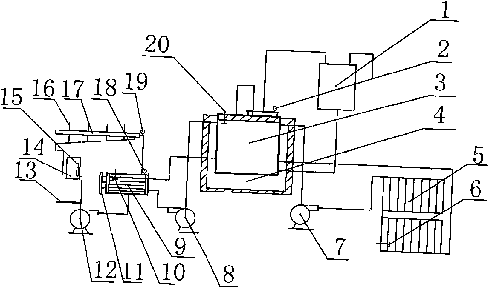
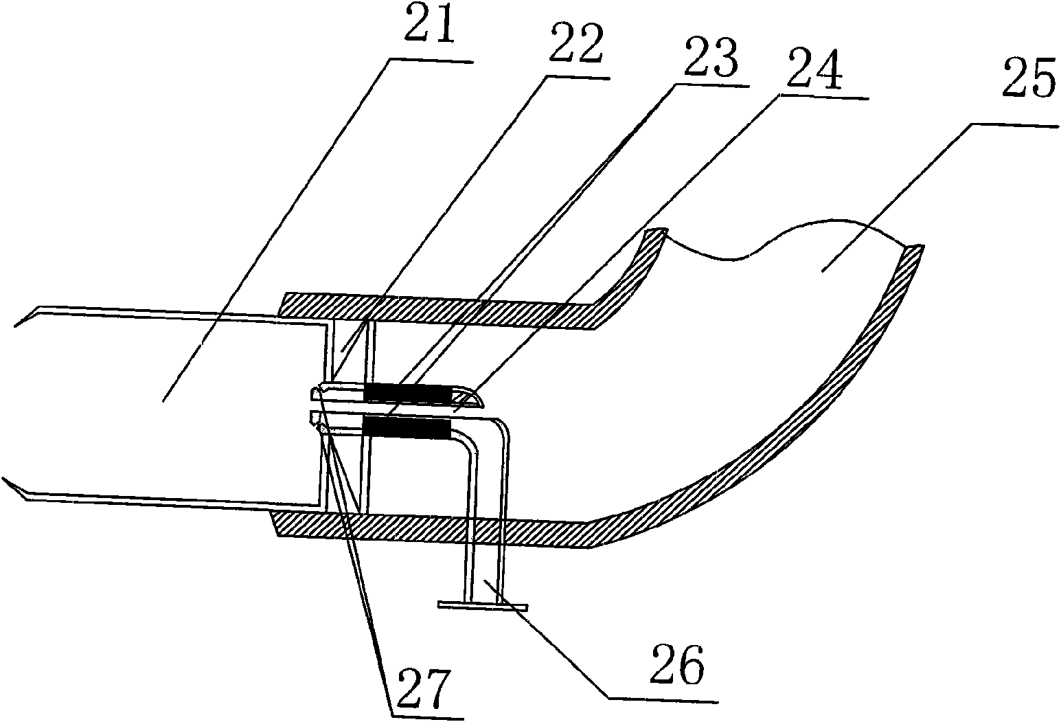

Image

  • Process and device thereof for vaporizing petroleum gas by heat transfer oil for ceramic industry
  • Process and device thereof for vaporizing petroleum gas by heat transfer oil for ceramic industry
  • Process and device thereof for vaporizing petroleum gas by heat transfer oil for ceramic industry

Examples


Embodiment 1

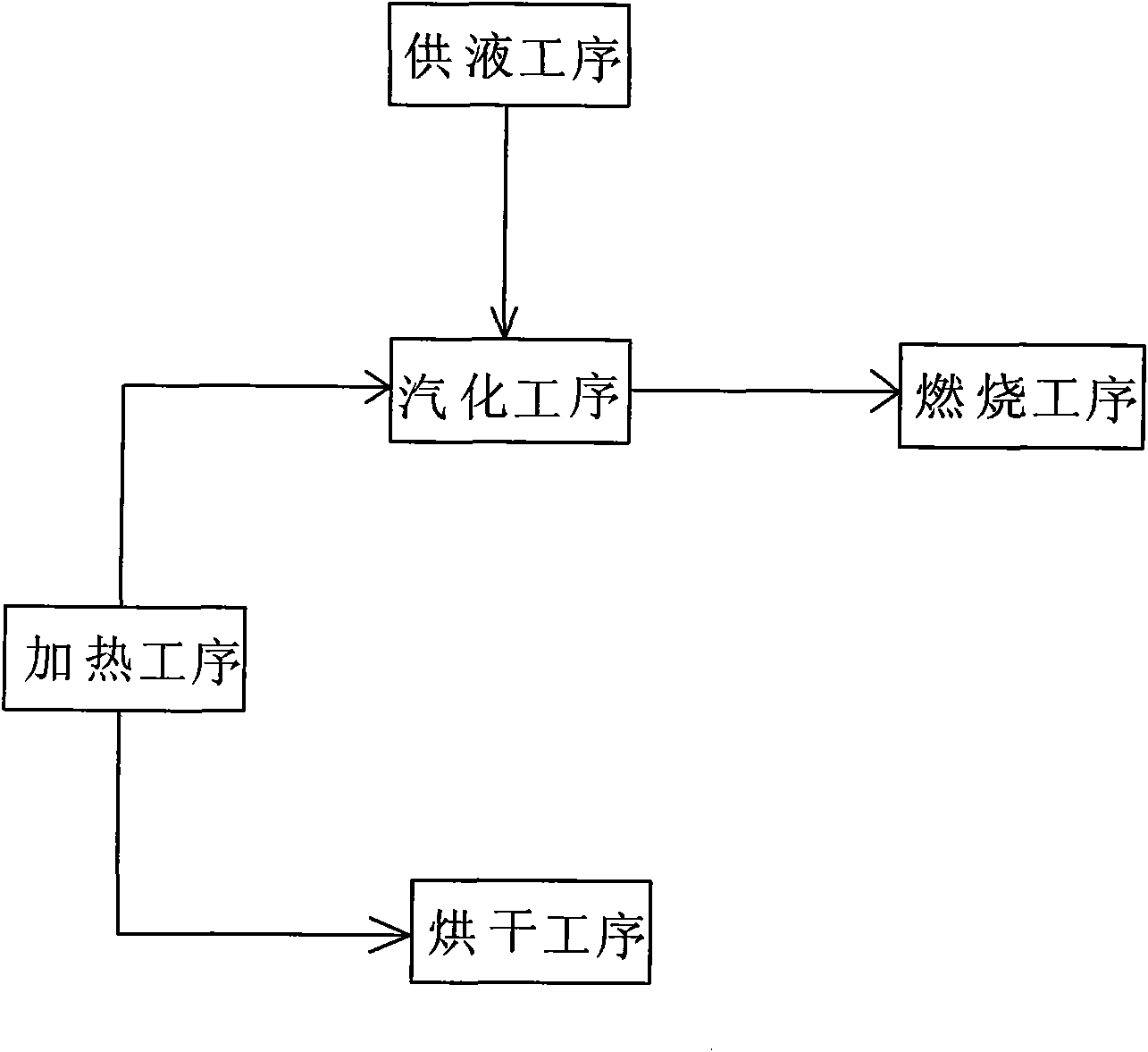
[0022] This embodiment is a process for vaporizing petroleum gas with heat transfer oil for the ceramic industry, such as image 3 As shown, it includes five steps: liquid supply process, heating process, vaporization process, drying process and combustion process. Enter the vaporizer, drying room and heat-conducting oil furnace until the oil level of the overflow barrel reaches 1 / 10 of the height of the barrel, control the temperature in the heat-conducting oil furnace at 250°C to 300°C, and heat the heat-conducting oil; After the temperature reaches the set value, start the heat-conducting oil circulation pump of the drying equipment, pump the high-temperature heat-conducting oil into the exhaust pipe of the drying room, and heat the drying room. When drying the ceramic mold, the temperature of the drying room is controlled at 65 ℃ ~ 75 ℃, when drying the ceramic body, the temperature of the drying room is controlled at 80 ℃ ~ 90 ℃; at the same time, the high temperature hea...


PUM


Abstract

The invention relates to a process and a device thereof for vaporizing petroleum gas by heat transfer oil for the ceramic industry. The process comprises a liquid supply procedure, a heating procedure, a vaporizing procedure and a burning procedure, and also comprises a drying procedure, wherein in the drying procedure, the drying temperature of a ceramic die is between 65 and 75 DEG C, and the drying temperature of a ceramic blank is between 80 and 90 DEG C. The device comprises a vaporizing part, a heating part, an automatic control part, a burning part, a liquid supply part and a drying part, wherein the vaporizing part comprises a vaporizer, the burning part comprises a burner, the liquid supply part comprises a liquid storage tank, the drying part comprises a drying room, and the heating part comprises a heat transfer oil furnace; a heating source is arranged in the heat transfer oil furnace which is connected with an overflow barrel through a pipeline; an output end of the heat transfer oil furnace is connected with the vaporizer and the drying room through the pipeline and a circulating pump respectively; and the vaporizer and the drying room are connected with the heat transfer oil furnace through respective output pipes respectively to form a heat transfer oil circulating loop.

Description

technical field [0001] The invention relates to a technology capable of keeping light hydrocarbons vaporized, in particular to a technology and equipment for vaporizing petroleum gas with heat-conducting oil used in the ceramic industry. Background technique [0002] At present, the environmental pollution caused by waste gas discharged in industrial production is becoming more and more serious, and the development of energy-saving and environmentally friendly fuels has become the goal pursued by people. Light hydrocarbons, as by-products of the petroleum industry, have received more and more attention. In recent years, people have been making attempts to use light hydrocarbons as raw materials for liquefied gas, such as adding methanol, methyl formate, ether, etc., because these substances have Toxicity, its use has been banned. Another method is to transport the light hydrocarbons side by side with the heating pipe, and use the heat of the heating to heat the light hydroc...

Claims


Application Information

Patent Timeline
IPC IPC(8): F23K5/22F23C5/00F26B9/06F24H7/00
Inventor 王玖兴肖秀钗方国良
Owner 方国良
Learn More