Controllable electromagnetic coupling microstrip split-ring resonator filter

A split-ring resonator and electromagnetic coupling technology, which is applied in the direction of resonators, circuits, electrical components, etc., can solve the problems that the transmission zero point cannot be independently controlled, the main coupling filter cannot realize the quasi-elliptic function filtering characteristics, and the volume is large. Achieve the effect of flexible transmission zero point setting, superior performance and small size

Inactive Publication Date: 2009-12-09
SOUTH CHINA UNIV OF TECH
View PDF0 Cites 15 Cited by
  • Summary
  • Abstract
  • Description
  • Claims
  • Application Information

AI Technical Summary

Problems solved by technology

[0005] The purpose of the present invention is to overcome the problem that the existing main coupling filter cannot realize the quasi-elliptic function filtering characteristics, overcome the problem that the existing cross-coupling filter is still large and the transmission zero point cannot be independently control

Method used


Image

  • Controllable electromagnetic coupling microstrip split-ring resonator filter
  • Controllable electromagnetic coupling microstrip split-ring resonator filter
  • Controllable electromagnetic coupling microstrip split-ring resonator filter

Examples


Embodiment 1

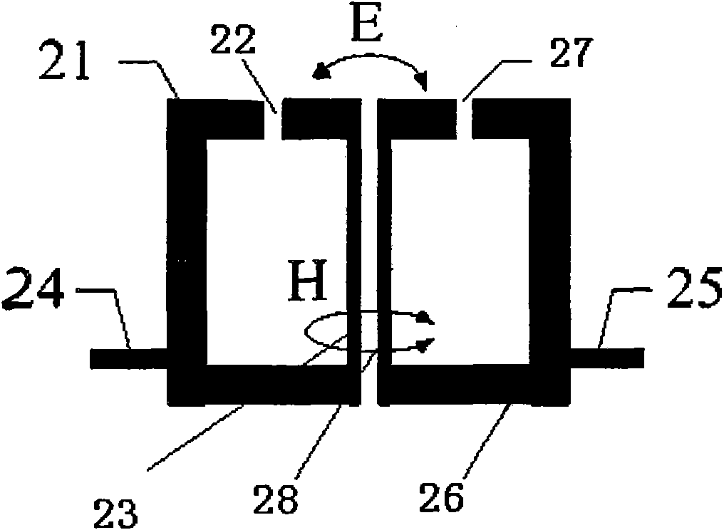
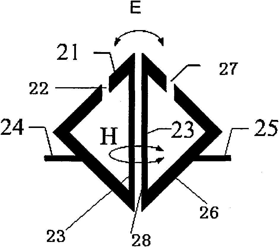
[0028] The structure of the second-order controllable electromagnetic coupling microstrip split ring resonator filter of the present invention is as follows Figure 2a ~ Figure 2b shown, where Figure 2a is a schematic diagram of the second-order controllable electromagnetic coupling rectangular microstrip split-ring resonator filter, Figure 2b It is a structural schematic diagram of a second-order controllable electromagnetic coupling triangular microstrip split ring resonator filter, including two resonators 21, 26, a signal input microstrip line 24 and a signal output microstrip line 25. The effective length of the resonators 21, 26 is half the operating wavelength of the second-order controllable electromagnetic coupling microstrip split ring resonator filter, and an opening 22 is provided at the top of the side adjacent to the coupling side 23 in the resonator 21 , the top of one side adjacent to the coupling side 28 in the resonator 26 is provided with an opening 27, a...

Embodiment 2

[0031] The fourth-order controllable electromagnetic coupling rectangular microstrip split ring resonator filter including two controllable electromagnetic coupling filter units is as follows: image 3 As shown, it includes four resonators 31-34, the signal input microstrip line 24 and the signal output microstrip line 25, the resonators 31 and 32 form a controllable electromagnetic coupling filter unit, and the resonators 33 and 34 form another controllable In the electromagnetic coupling filter unit, four resonators 31-34 are arranged in a straight line. The effective lengths of the resonators 31 to 34 are half the working wavelength of the filter, the top of the resonator 31 adjacent to the coupling side 35 is provided with an opening 39, and the side of the resonator 32 adjacent to the coupling side 36 An opening 40 is provided at the top of the top, and the positions of the openings 39 and 40 can be adjusted on the side where the openings 39 and 40 are located according t...

Embodiment 3

[0034] A third-order controllable electromagnetic coupling triangular microstrip split-ring resonator filter including a controllable electromagnetic coupling filter unit is shown as Figure 4 As shown, it includes a ladder impedance resonance unit 43, two triangular split ring resonators 44, 45, signal input microstrip line 24 and signal output microstrip line 25, and two resonators 44, 45 form a controllable electromagnetic coupling filter unit. The effective lengths of the resonators 44 and 45 are half the operating wavelength of the filter, and the top of the adjacent side of the resonator 44 and the coupling side 46 is provided with an opening 48, and the position of the opening 48 can be adjusted according to the electric, The magnetic coupling ratio is adjusted on its side; the top of the resonator 45 adjacent to the coupling side 47 is provided with an opening 49, and the position of the opening 49 can be on its side according to the electric and magnetic coupling rati...


PUM


Abstract

The invention is a controllable electromagnetic coupling microstrip split-ring resonator filter, comprising an input microstrip, an output microstrip and a microstrip resonator group, wherein the microstrip resonator group is one or more than one controllable electromagnetic coupling filter unit(s); the controllable electromagnetic coupling filter unit comprises two mutually coupled resonators, and the effective length of each resonator is as half as the work wave-length of the controllable electromagnetic coupling microstrip split-ring resonator filter; an opening is arranged at the top or bottom at a side of each resonator in the same controllable electromagnetic coupling filter unit; the opening positions of the two resonators are simultaneously positioned at the tops or the bottoms of the resonators, the edge on which the opening is located is adjacent to the coupled edges of the two resonators; and the positions of the two openings are centrosymmetric corresponding to the centerline of two coupled edges which is formed by a high-impedance line. The filter of the invention can achieve quasi-elliptic function filter characteristic, and has compact structure, small volume, low cost and good properties.

Description

technical field [0001] The invention relates to a microstrip filter, in particular to a microstrip split ring resonator filter with controllable electromagnetic coupling. Background technique [0002] Microwave filters play a very important role in wireless signal processing, which can filter out interference signals and pass useful signals. Due to the advantages of small size, light weight, easy processing, and easy integration, microstrip filters with quasi-elliptic function responses are widely used in circuit modules of various wireless communication systems. The high-temperature superconducting film has a surface resistance close to zero and has a very high quality factor (Q value). The quasi-elliptic function microstrip filter made of the high-temperature superconducting film has extremely low passband loss and is suitable for mobile Communication base station system. After the mobile communication base station uses high-temperature superconducting filters, it can in...

Claims


Application Information

Patent Timeline
IPC IPC(8): H01P1/203H01P7/08
Inventor 褚庆昕王欢
Owner SOUTH CHINA UNIV OF TECH
Why Eureka
Try Eureka