Bionic coupling blade of aerogenerator

A technology for wind turbines and blades, which is applied to wind turbine components, wind turbines, wind power generation, etc., can solve the problem of reducing the structural safety of the blades and the stability of their functions, affecting the direction of the blade jet, and affecting the performance of the wind turbine. and other problems, to achieve the effect of reducing instability, reducing area, and weakening the intensity of turbulent bursts

Inactive Publication Date: 2009-12-16
JILIN UNIV +1
View PDF3 Cites 4 Cited by
  • Summary
  • Abstract
  • Description
  • Claims
  • Application Information

AI Technical Summary

Problems solved by technology

But there are also some problems when implementing this technology, for example, in the case of variable pitch, any slight change in the pitch angle will affect the direction of the jet on the blade relative to the plane of rotation, which will obviously affect the performance of the wind turbine
[0004] CN 1415854A adopts the method of setting wing knives on the windward surface of the blades, so that the direction of the wing knives is consistent with the cross-section of the blades and perpendicular to the blade surface, and the radial airflow of the blades is reduced by using the blocking effect of the wing knives on the airflow, so that the airflow The loss of kinetic energy is reduced and more is transformed into the propulsion to the blade, but the installation of wing blades on the blade actually reduces the safety of the blade structure and the stability of its function
[0005] However, as far as the blade is concerned, the airflow acts on the blade surface against the wind, and the force of the airflow is decomposed into positive pressure and lateral thrust. The lateral thrust is expressed as the driving force for the rotation of the blade. It is smooth, so that the airflow on the blade surface forms a radial flow from the center to the blade tip. Such airflow will reduce the efficiency of the blade, and a certain distance must be kept between every two wind turbines to avoid Reduced work efficiency due to the influence of eddy currents

Method used


Image

  • Bionic coupling blade of aerogenerator
  • Bionic coupling blade of aerogenerator
  • Bionic coupling blade of aerogenerator

Examples


Embodiment 1

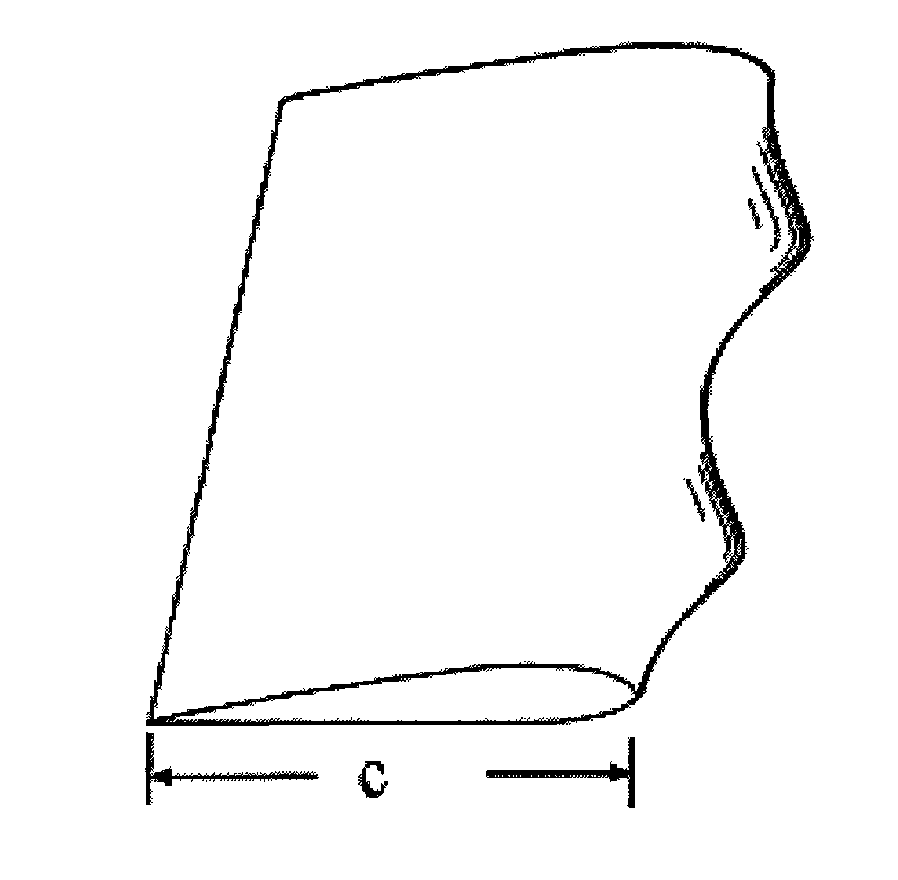
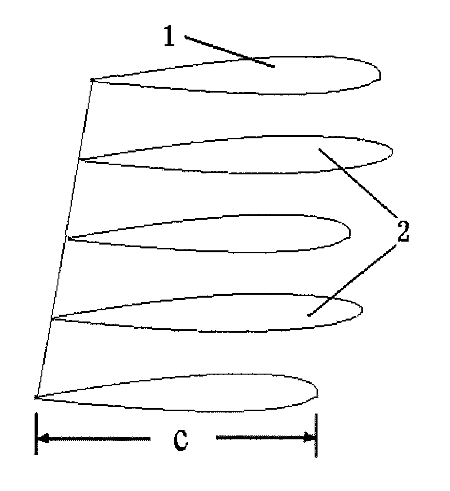
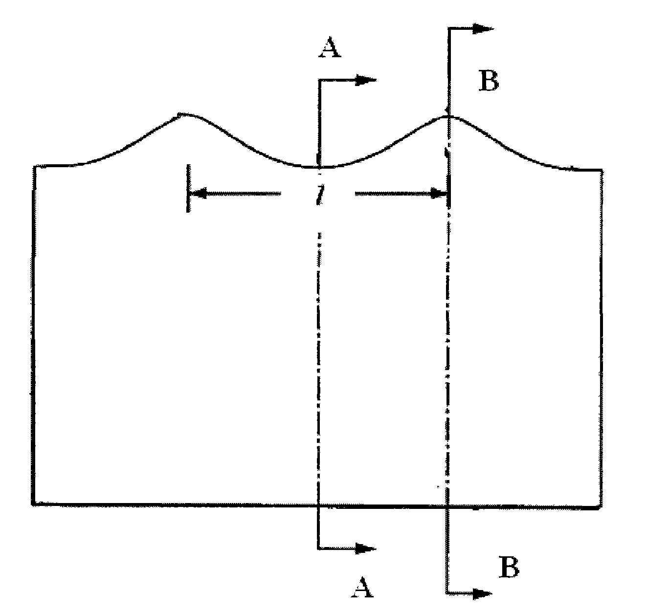
[0024] Referring to Figures 1 and 2, taking NACA 0018 (NACA: (USA) National Aviation Advisory Committee) airfoil as an example, at Reynolds number Re=2.5×10 5 , (Re=VC / v, where V: incoming flow velocity, C: chord length, v: fluid kinematic viscosity) the surface of the bionic coupling structure at the leading edge of the blade spread, the distance from the trough to the trailing edge is defined as the airfoil The basic chord length C, the distance from the peak to the trailing edge is 1.025 times the basic chord length C of the airfoil; the distance wavelength l from the trough to the trough (peak to peak) is 0.25 times the basic chord length C of the airfoil; there is a bionic coupling leading edge (Figure 1) has a 3.7% increase in lift and a 6.1% decrease in drag compared to a smoother leading edge (Figure 2).

Embodiment 2

[0026] Referring to Figures 1 and 2, taking NACA 0018 as an example, at Re=2.5×10 5 , the surface of the bionic coupling structure at the leading edge of the blade span, the distance from the trough to the trailing edge is set as the basic chord length C of the airfoil, and the distance from the peak to the trailing edge is 1.025 times the basic chord length C of the airfoil; the trough to the trough The distance wavelength l (peak to peak) is 1.0 times of the basic chord length C of the airfoil; the lift force of the bionic coupling leading edge (Fig. 1) is 5.3% higher than that of the leading edge smooth (Fig. 2), and the drag is reduced by 8.9%. .

Embodiment 3

[0028] Referring to Figures 1 and 2, taking NACA 0018 as an example, at Re=2.5×10 5 , the surface of the bionic coupling structure at the leading edge of the blade span, the distance from the trough to the trailing edge is set as the basic chord length C of the airfoil, and the distance from the wave crest to the trailing edge is 1.2 times the basic chord length C of the airfoil; The distance wavelength l (from peak to peak) is 0.25 times of the basic chord length C of the airfoil; the lift with bionic coupling leading edge (Fig. 1) is 10.1% higher than the smooth leading edge (Fig. 2), and the drag is reduced by 13.7%. .


PUM


Abstract

The invention relates to a bionic coupling blade of an aerogenerator, which belongs to the field of wind power equipment. The invention is a bionic coupling blade structure of the aerogenerator, namely airfoil profiles (configurations) are coupled with a blade structure. Through the research on arrangement modes of wing feathers of wings of typical birds (long-eared owl and the like), based on a biological function coupling principle, the airfoil profiles are sequentially arranged to form the surface of a bionic coupling structure at the spanwise front edge of a blade to ensure that the blade has the characteristics of high lift and low resistance. The form of the spanwise front edge of the blade can be limited by three values, namely wave crest, wave trough and wavelength; the distance from the wave trough to a trail edge is set as a basic chord length C of the airfoil profiles; the distance from the wave crest to the trail edge is 1.025 to 1.20 times of the basic chord C of the airfoil profiles; and the distance wavelength I from the wave trough to the wave trough (the wave crest to the wave crest) is 0.25 to 1 time of the basic chord C of the airfoil profiles. The invention aims to reduce the vortex produced on the surface of the blade, improve the work efficiency of the blade, and effectively reduce the noise of the blade structure.

Description

Technical field: [0001] The invention relates to a blade structure of a wind power generator, which belongs to the field of wind power generation equipment. Background technique: [0002] Improving the utilization efficiency of wind energy of wind turbines has always been the goal that people are constantly pursuing. [0003] CN03134065.2 and CN 200952450Y propose to open jet holes on the surface of the blades, and the jet direction is the tangential direction of impeller rotation, that is, the so-called "thrust type working principle", which reduces the starting wind speed of the wind turbine, thereby expanding the wind turbine. The scope of work. But there are also some problems when implementing this technology. For example, in the case of variable pitch, any slight change in the pitch angle will affect the direction of the jet on the blade relative to the plane of rotation, which will obviously affect the performance of the wind turbine. [0004] CN 1415854A adopts the...

Claims


Application Information

Patent Timeline
IPC IPC(8): F03D11/02F03D1/06
CPCY02E10/722Y02E10/72
Inventor 任露泉徐成宇商延赓刘庆萍张志辉王志杰
Owner JILIN UNIV
Why Eureka
Try Eureka