
Realizing method of pi/2 phase bias of optical fiber interferometer

An optical fiber interferometer and phase offset technology, which is applied in the coupling of optical waveguides and the use of optical devices to transmit sensing components, which can solve the problems of increasing the difficulty of system implementation, phase difference, and inability to obtain the maximum linear working range.

Active Publication Date: 2009-12-23
FUDAN UNIV
View PDF0 Cites 8 Cited by
  • Summary
  • Abstract
  • Description
  • Claims
  • Application Information

AI Technical Summary

Problems solved by technology

The former method must apply electrical signals, which increases the complexity of the system
In the latter scheme, due to the phase difference brought by the 3×3 splitter 16 itself, although a non-zero offset phase can be obtained at the interference signal output terminals 18 and 19, the offset phase is only system is not working on where the maximum linear operating range cannot be obtained
Although this structure, the equivalent phase bias, but the optical insertion loss consistency of the two output channels is very good, and it also requires circuit processing, which increases the difficulty of system implementation

Method used


Image

  • Realizing method of pi/2 phase bias of optical fiber interferometer
  • Realizing method of pi/2 phase bias of optical fiber interferometer
  • Realizing method of pi/2 phase bias of optical fiber interferometer

Examples


Embodiment Construction

[0043] Construct a Sagnac interferometer whose phase offset is π / 2 with the method of the present invention, the structure is as Figure 7 shown. The port 24 of the splitter 23 is connected to a light source, which is a SO3-B superluminescent diode (SLD) stable light source produced by the 44 Research Institute of the Electronics Group Corporation. The 3×3 splitter 23 is a fused tapered single-mode fiber optic coupler manufactured by Shanghai Kangkuo, with a splitting ratio of 20%:40%:40%. The cross-section of the coupler is as Image 6 As shown, the three optical fibers form a triangular structure after being fused and tapered, and 39, 40, and 41 are their cross-sections respectively. The optical fiber ring 12 is formed by winding an optical fiber, and the optical fiber is a G652 type single-mode optical fiber produced by "Corning" in the United States. The photodetection device is connected to the port 26 of the coupler, which is an InGaAs photodetector produced by 44 and...


PUM


Abstract

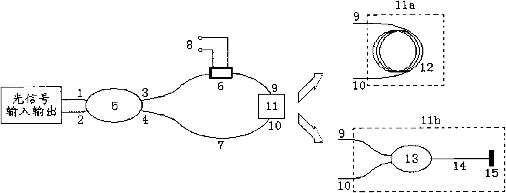
The invention belongs to the fields of optical fiber sensing and measuring technologies, in particular to a realizing method of the pi / 2 phase bias of an optical fiber interferometer. The phase bias is generated by arranging a special optical fiber branching unit with the length and the width of 3 in an interference optical path structure; the optical intensities of output ports of the branching unit are respectively 20 percent, 40 percent and 40 percent of total output light; and the pi / 2 phase bias can be obtained by a proper optical path connection. The invention realizes the pi / 2 (positive or negative) phase bias with a pour optical path method and obtains high measuring sensitivity and linear segment measuring range. The invention is not only suitable for an interference system with same interference optical paths and opposite transmission directions, such as interference systems of Sagnac rings, single-core feedback types, and the like, and can also provide the phase bias for an M-Z optical fiber interference structure.

Description

technical field [0001] The invention belongs to the technical field of optical fiber sensing and measurement, and in particular relates to a method for realizing π / 2 phase bias of an optical fiber interferometer. Background technique [0002] Optical fiber sensor is a sensor with optical fiber as functional material, which is the product of the development of laser technology and optical fiber communication technology. In recent years, due to the emergence of semiconductor lasers and low-loss optical fibers, fiber optic sensing technology has developed rapidly. [0003] The basic principle of optical sensors includes a variety of modulation techniques, including intensity modulation, frequency modulation, wavelength modulation, polarization modulation and phase modulation. Phase modulation, that is, interferometric optical sensors, has extremely high sensitivity and high precision. , occupies an important position in the field of optical sensing. [0004] The traditional o...

Claims


Application Information

Patent Timeline
Patent Type & Authority Applications(China)
IPC IPC(8): G01D5/26G02B6/26
Inventor 贾波肖倩
Owner FUDAN UNIV
Learn More